Millennium Falcon Build Journal No. 24: Issues 85-88
![]() Trader Sam | April 13, 2017
Trader Sam | April 13, 2017
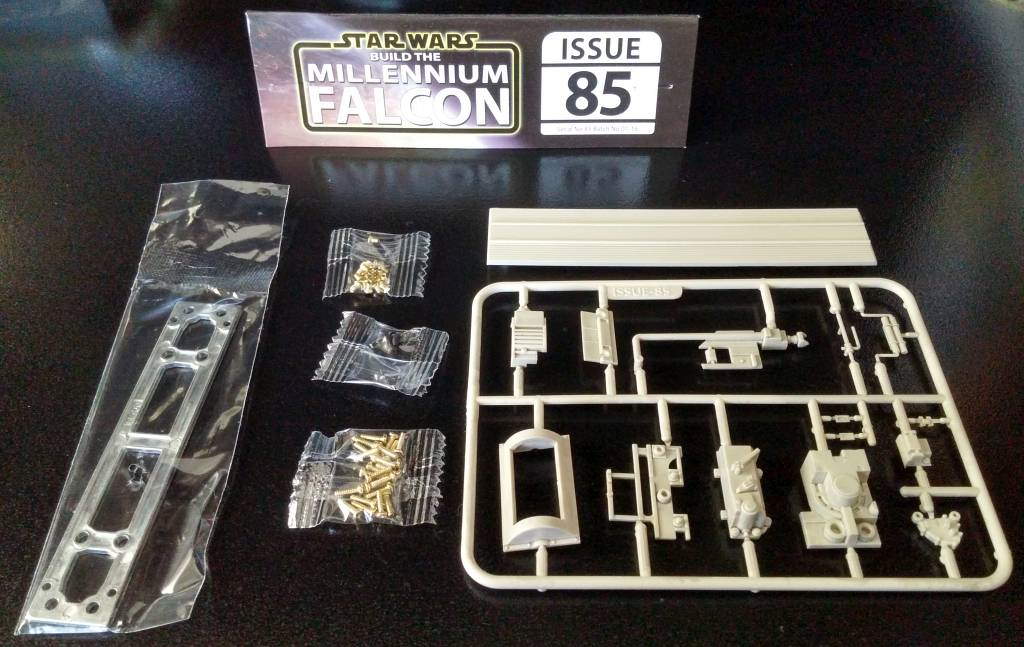
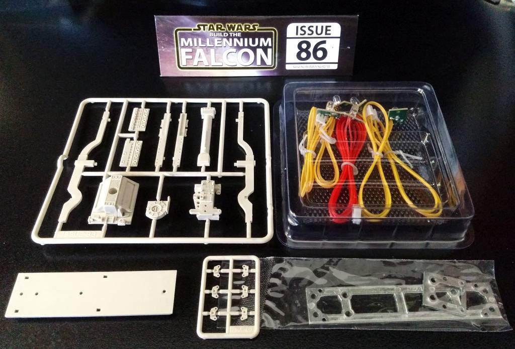
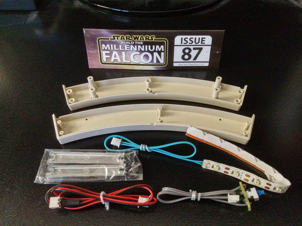
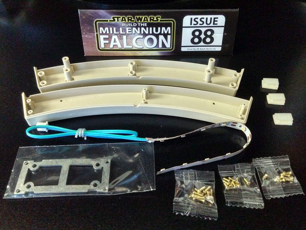
The Contents


The port mandible is “completed” (there are more parts to assemble next month), and some more lights get installed. I also get my second defective part, and I learn a valuable lesson.

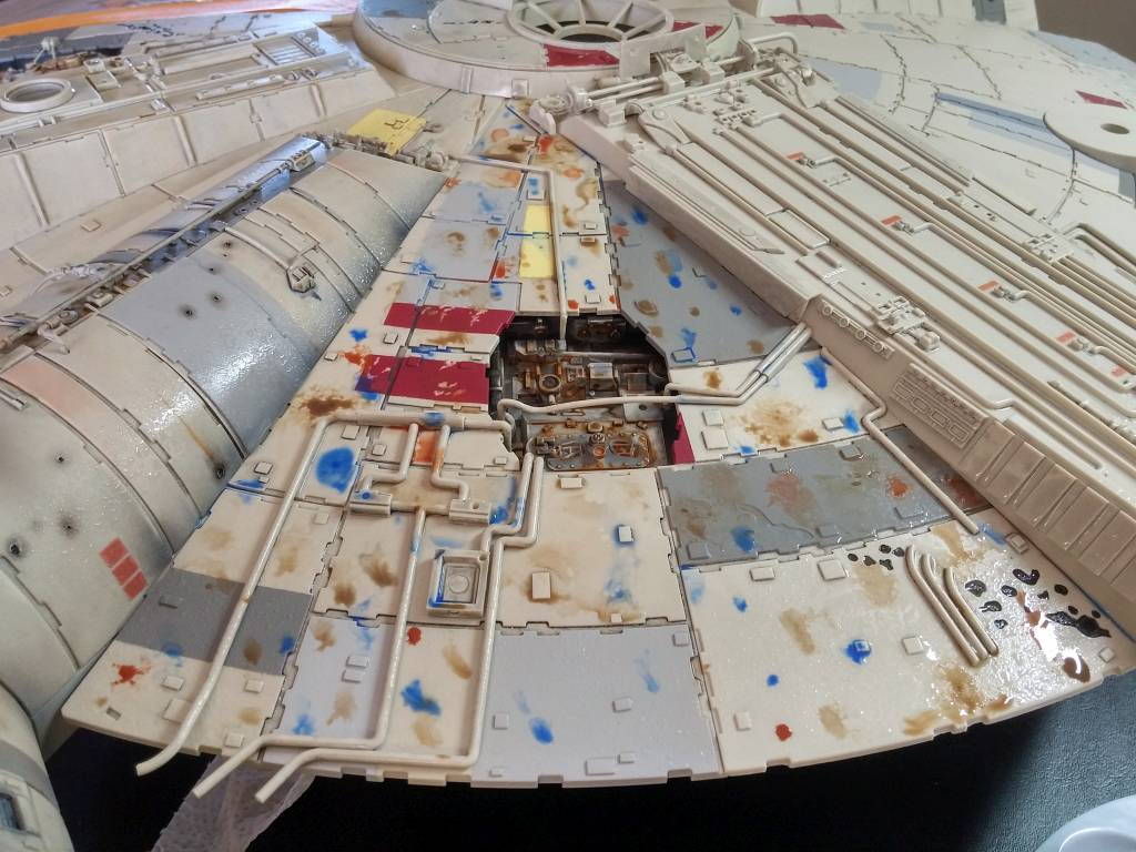
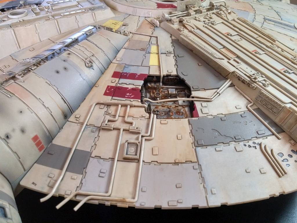
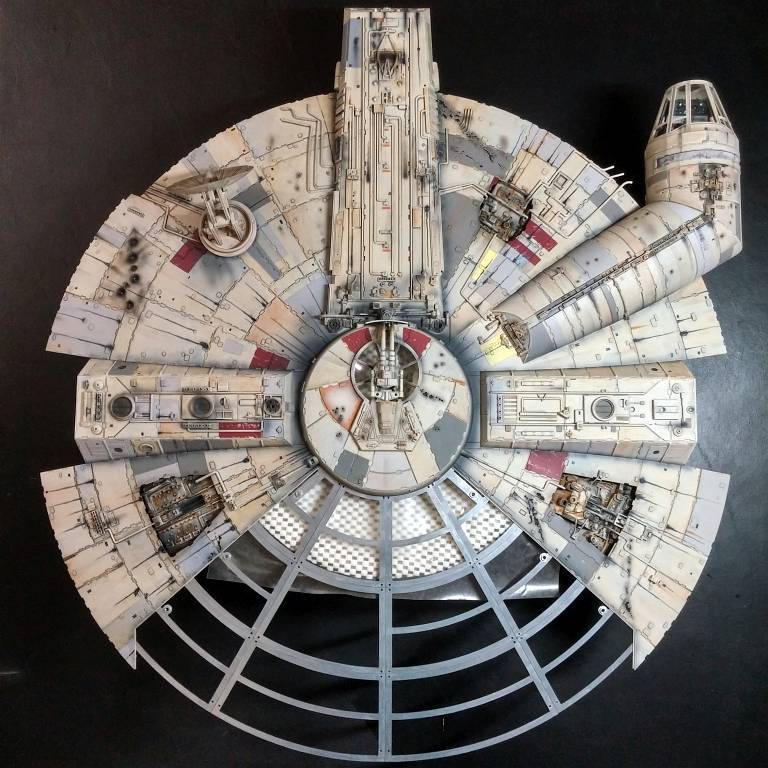
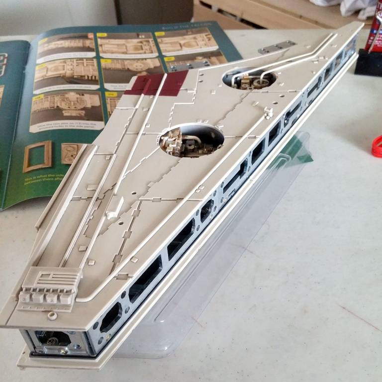
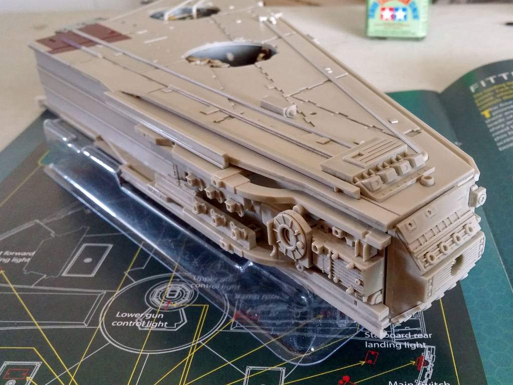
Painting the Upper Hull
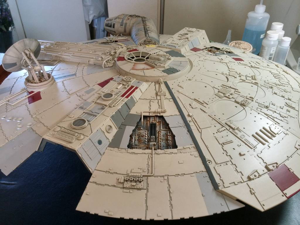
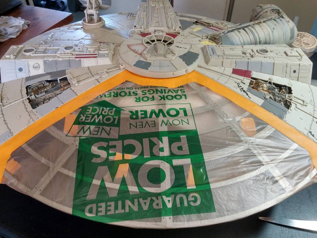
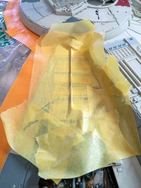
I couldn’t take it any more! I had already painted the rectenna dish and the cockpit tube several months before, and I’ve been itching to paint the upper hull. But, the final pieces for the engine cover arrive in the final packages. So, I removed the engine cover and masked it off.
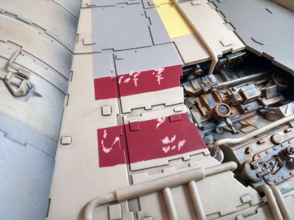
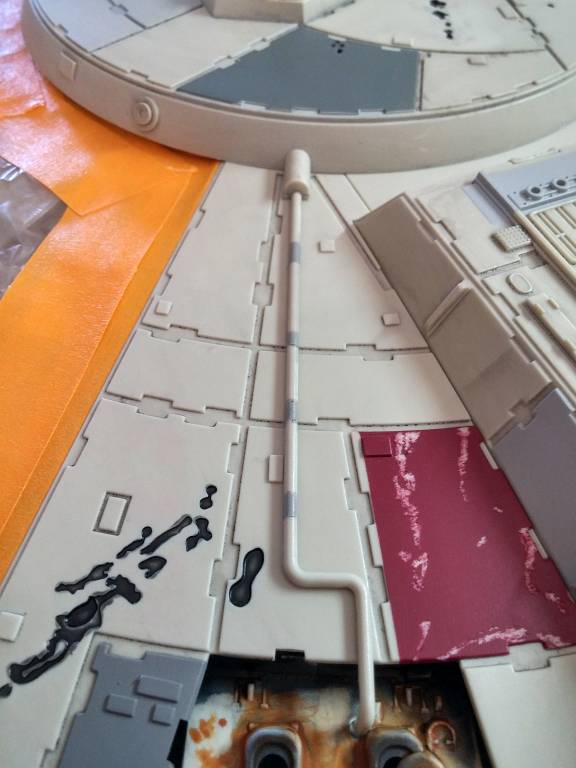
I used a cheap engraver to chip away paint. As I did so, I discovered that I had missed some tube markings. Rather than set up my airbrush for such tiny markings, I painted them by hand. Then, I proceeded to dirty up the hull, distress, paint, and varnish it as before.
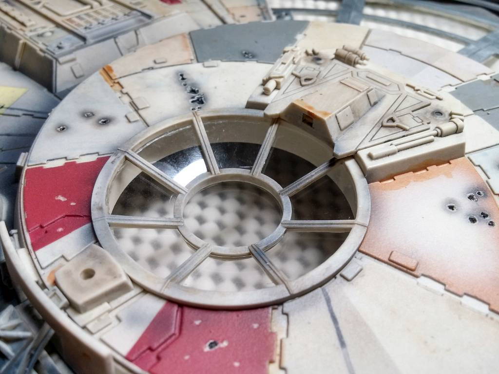
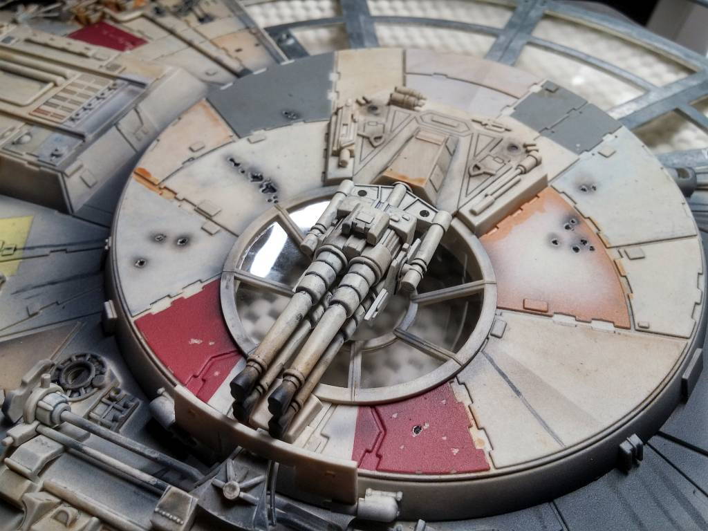
Using the window template that I created, I installed the window panes on the turret window. The finishing touch was adding the quad laser, which was such a snug fit that it did not require any glue.
Reinstalling the engine cover, I discovered that it was much easier to screw in. Being attached to the metal framework seems to have bent it into its proper shape.
Wire Organization & Testing
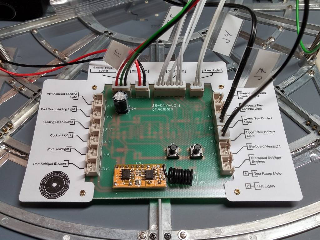
To help keep with wire organization and to keep things clear for future servicing, I made a couple of tweaks. First, I designed a Circuit Connections Key.
Printed on card stock, the Circuit Connections Key clearly identifies what each socket is connected to; it simply screws on top of the circuit board. Now, I will not have to refer to any of the magazines to fix any connections.
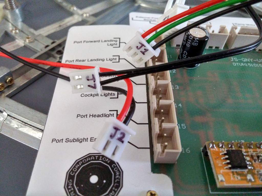
I also removed the bulky wire tags and simply wrote the connections on the ends of the plugs with a fine tip Sharpie.
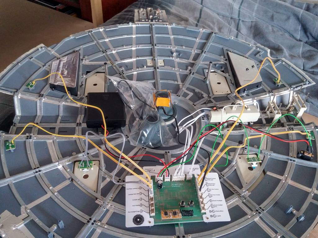
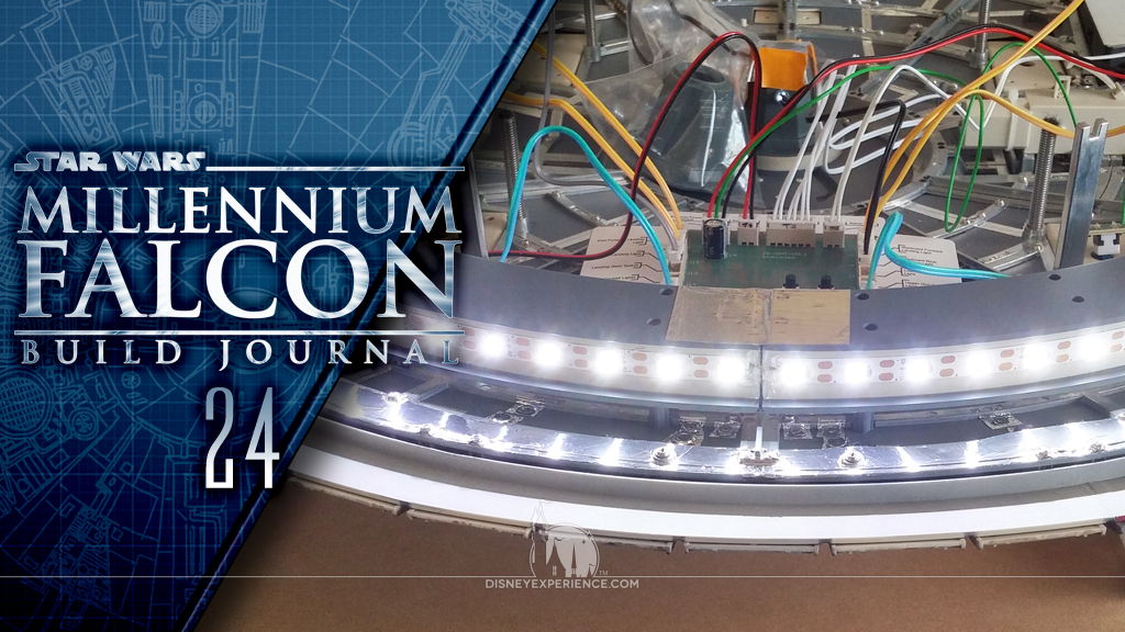
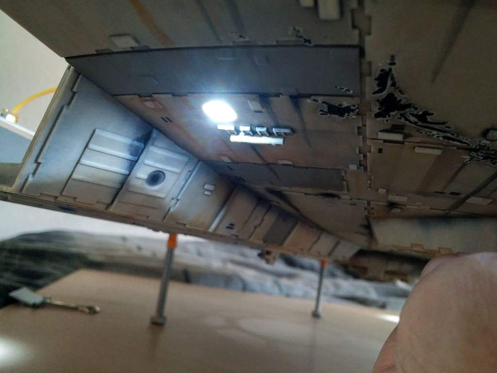
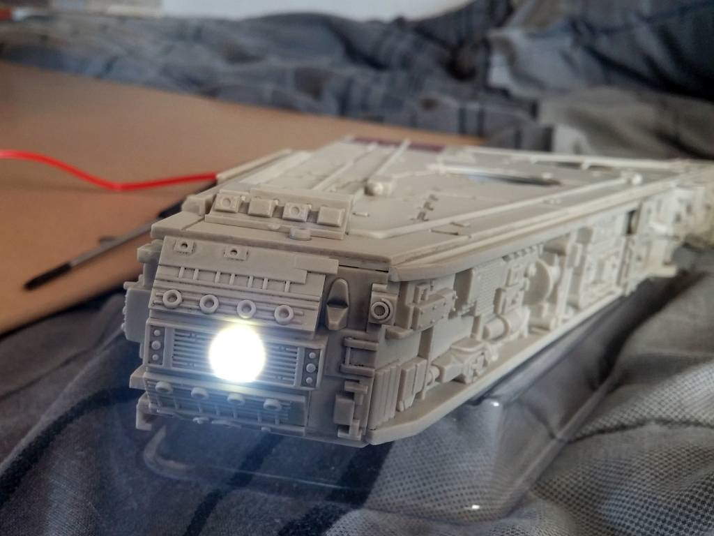
Now was the time to install and test the four landing lights.
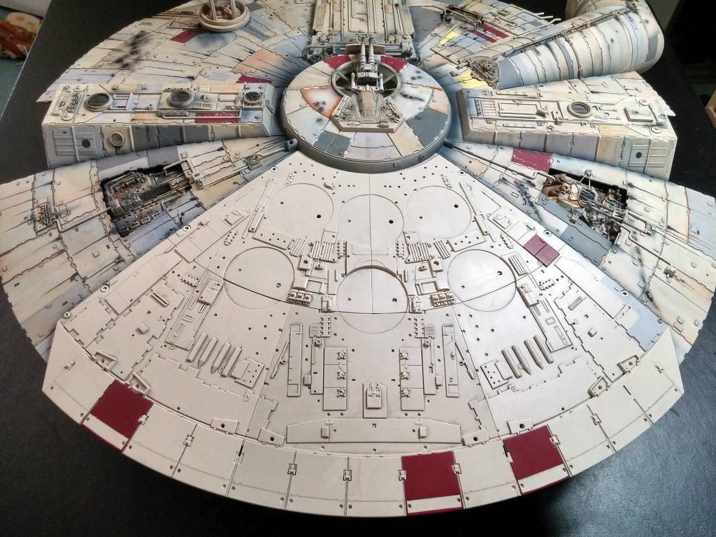
Assembling the Port Mandible
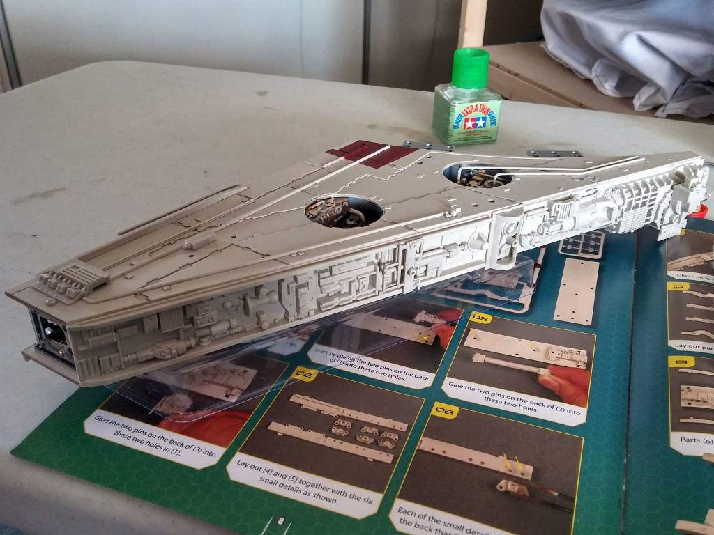
More parts are provided to “complete” the port mandible. There will be more greeblies in next month’s package, but both mandibles can essentially be called completed . . . aside from painting them, of course.
Jumping Ahead
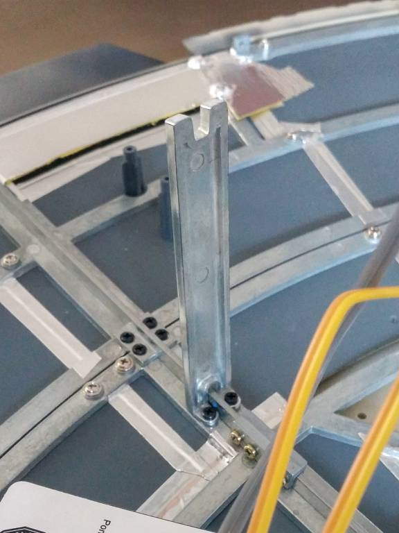
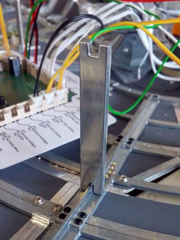
Rather than waiting, I attached the two rear support beams and the first side frame.
They’re not much, but at least I don’t have any extra parts lying around waiting to be lost or broken.
Sublight Engines & A Lesson Learned
The sublight engines were the most anticipated part of this month’s assembly. I’ve seen other people follow DeAgostini‘s assembly directions and fail. But, the fault lies with how DeAgostini has chosen to assemble the engine lights.
Assembling the engine lights by way of the instructions results in a dim, visible gap in the center of the engine lights. It’s most noticeable when the diffuser strip is installed (next month), and it almost looks like there is a burned-out LED. Trust me, it’s ugly and annoying.
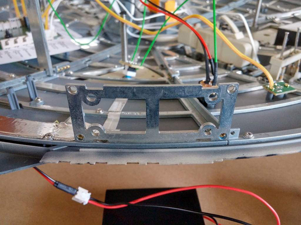
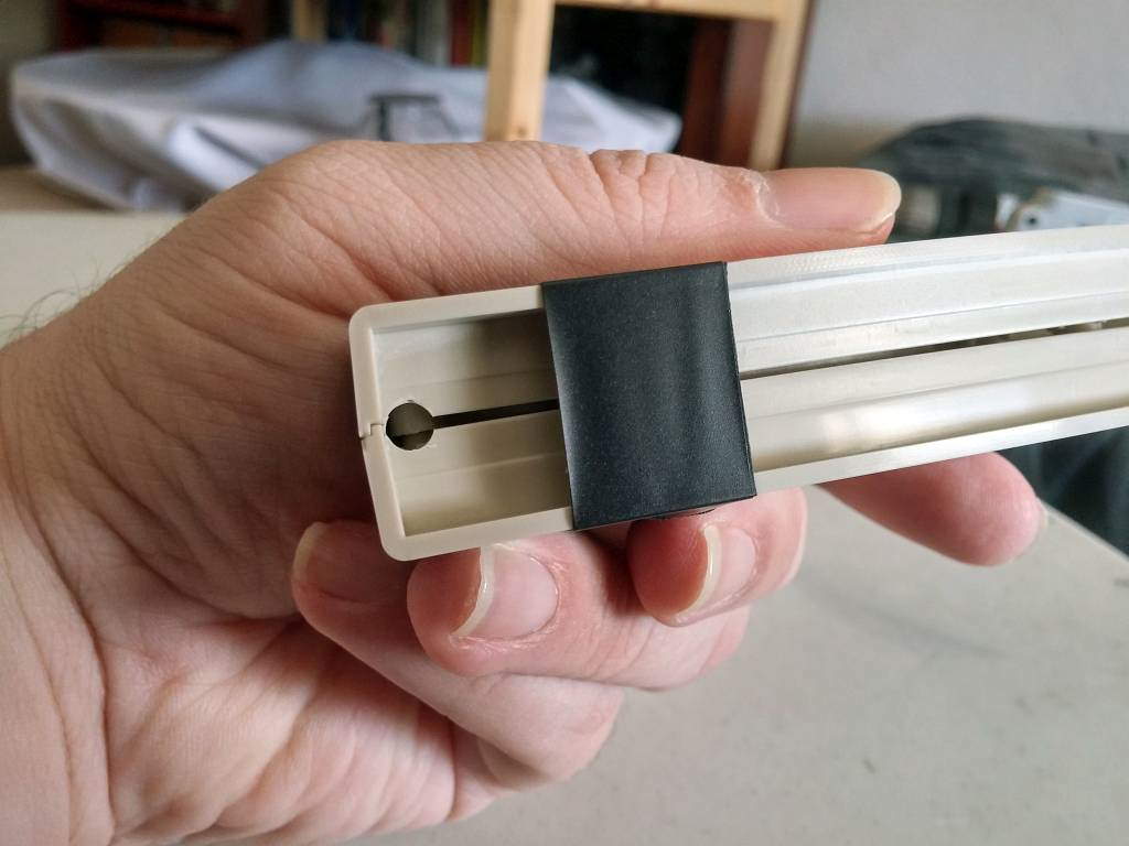
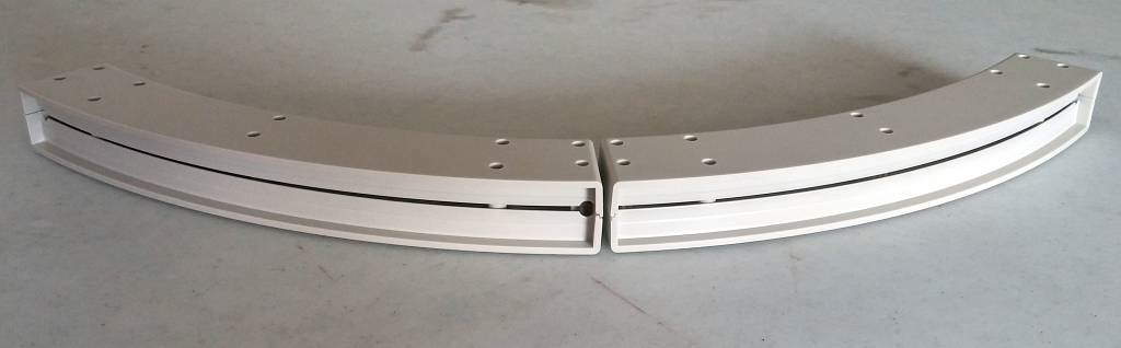
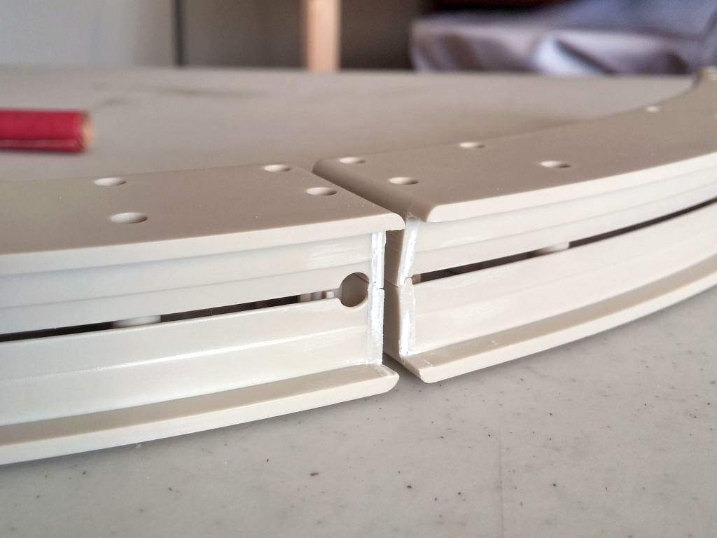
I began to fix the problem by drilling a hole in the opposite end of one of the light housings. This way, I could create mirror copies of the housings and butt up the ends of the LED strips. Then, I cut away the two walls where the housing meet in the center.
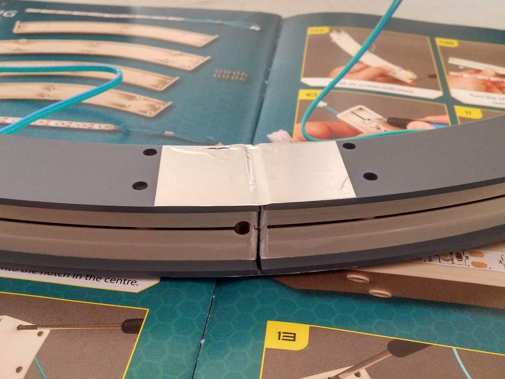
I spray painted the housings to light-block them, assembled them, and then I dry-fitted them onto their lower hull posts. Once in position, I carefully connected them with a piece of aluminum tape to essentially create one large housing. The tape blocks the light from leaking between the housings, and it keeps the parts secure while I measure and mark for the next step.
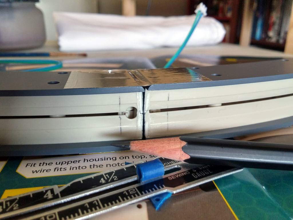
Measuring the spacing of the LEDs on the strips, I got a measurement of roughly 17mm. With that, I marked 8.5mm from each side of the housing center.
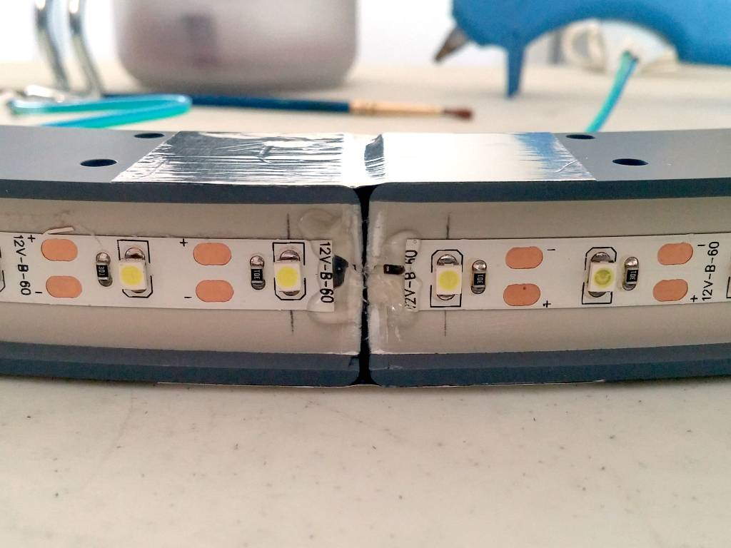
I lined up the last LEDs on each strip, centering them on the penciled markings, and I adhered them to the surface. Now, I’m not very trusting of 3M adhesives, so I decided to hot-glue the ends down . . . particularly the wires.
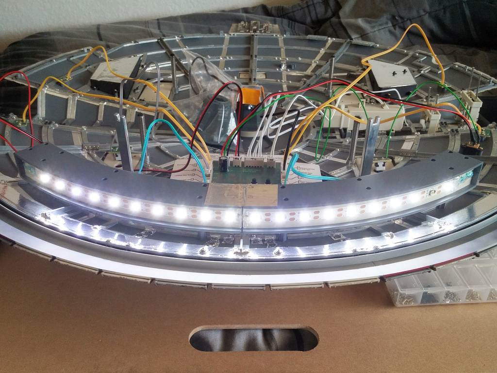
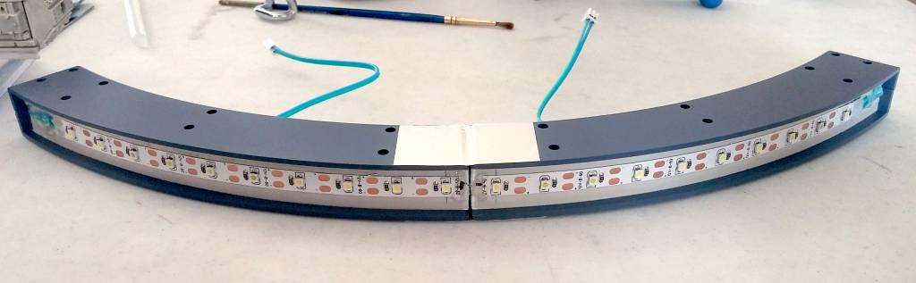
I permanently screwed the light housing onto the lower hull, plugged the two wires in, and tested the lights with success. I had a nice, steady stream of lights with no break in the middle . . .
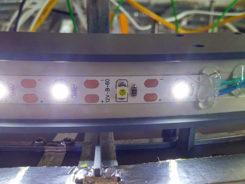
. . . except for the dead LED on the far right. Sigh.
This is what happens when I break my own rule: always check the lights before installing them. I wanted to believe that the lights would work without fail, so I never tested them. Now, I will have to disassemble one side of the housing to install a replacement LED strip.
This is only the second time that I’ve had to request a replacement part, so kudos to DeAgostini. I honestly thought I would have needed more replacement parts by now.
Prev Journal Entry | Next Journal Entry
Both the post author and this website have not received any compensation for writing this post. Both the post author and this website have no material connection to the third-party brands, products, or services that have been mentioned. Some of the links in the post above are “affiliate links.” This means that if you purchase the item, we will receive a commission. As an Amazon associate, we earn from qualifying products. This is being disclosed in accordance with the Federal Trade Commission’s 16 CFR, Part 255: “Guides Concerning the Use of Endorsements and Testimonials in Advertising.”
Do you have a thought about this post? Why not leave a comment . . .