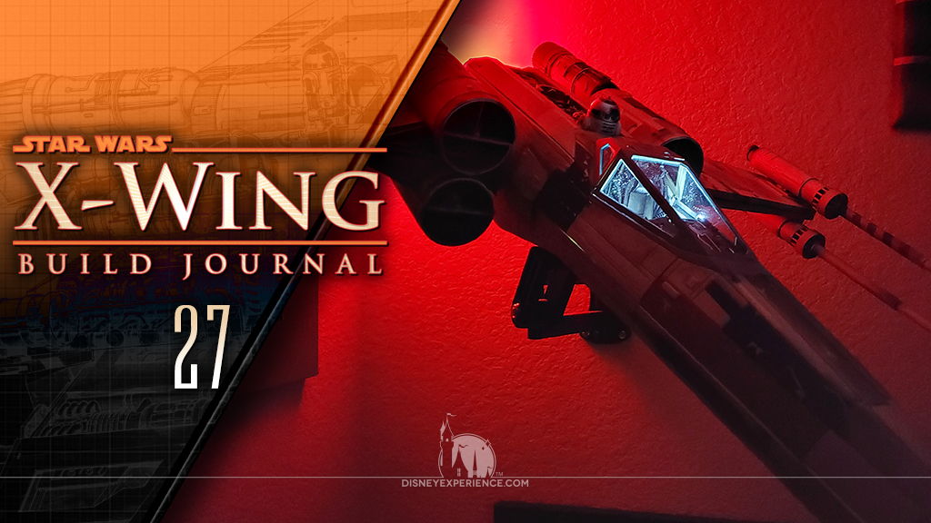
X-Wing Build Journal No. 27: Issues 97-100
Trader Sam | May 10, 2021
What’s Inside
The X-Wing model is finally finished; whew! And, the diorama set has arrived in the mail.


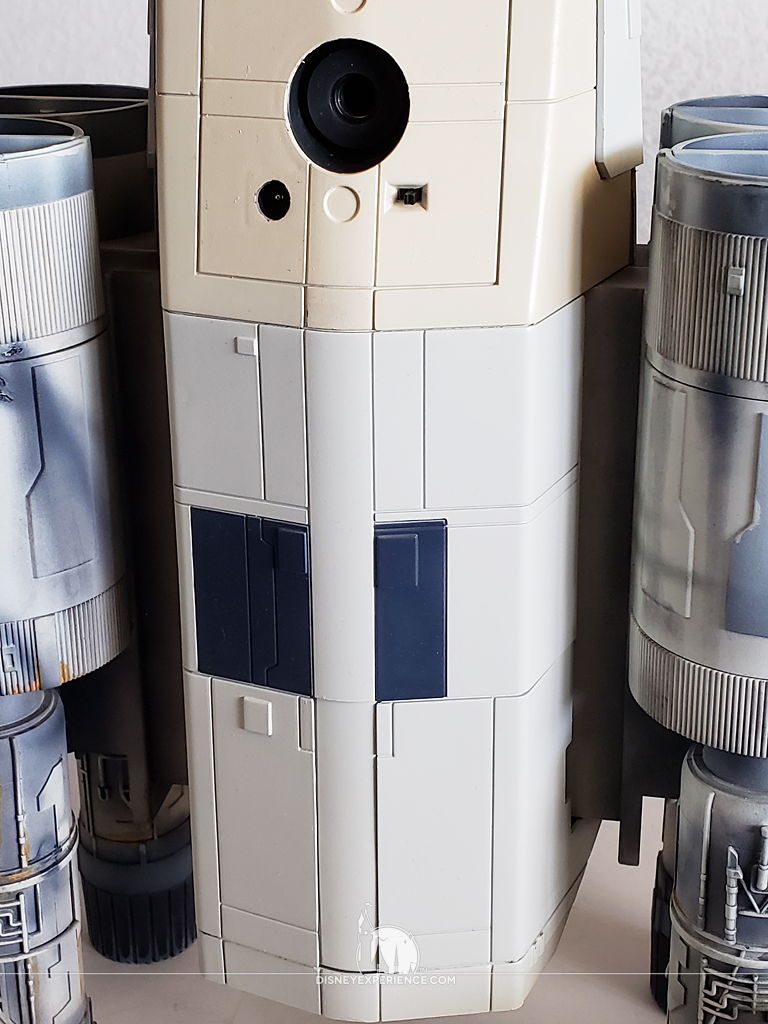
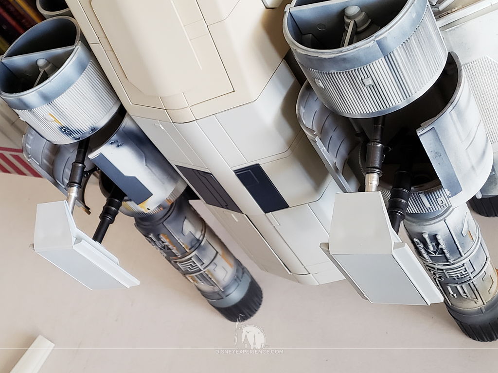
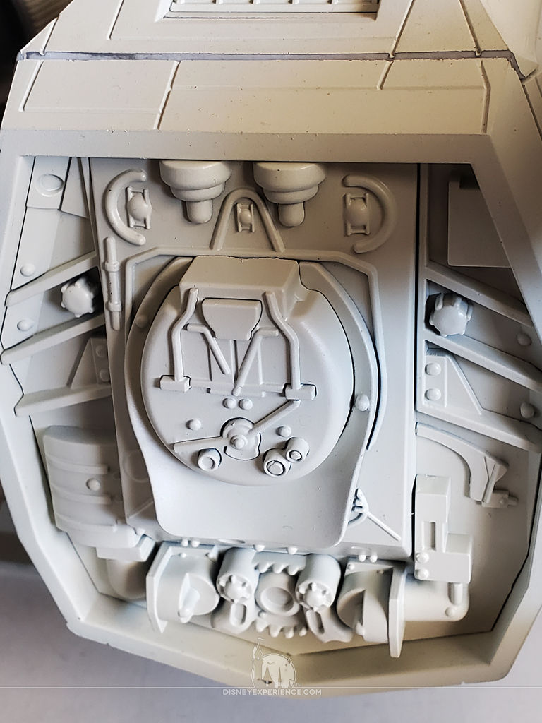
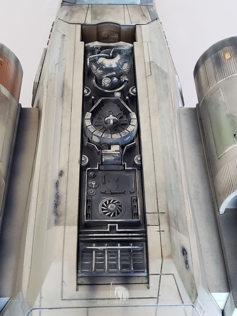
Rear Fuselage Details
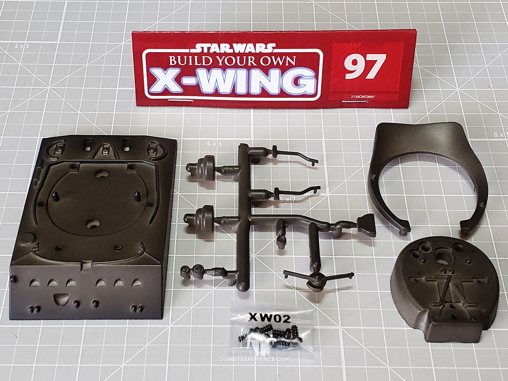
I did the final wash on the plastic pieces. I separated the landing legs and a nose panel, all of which I did not want to paint.
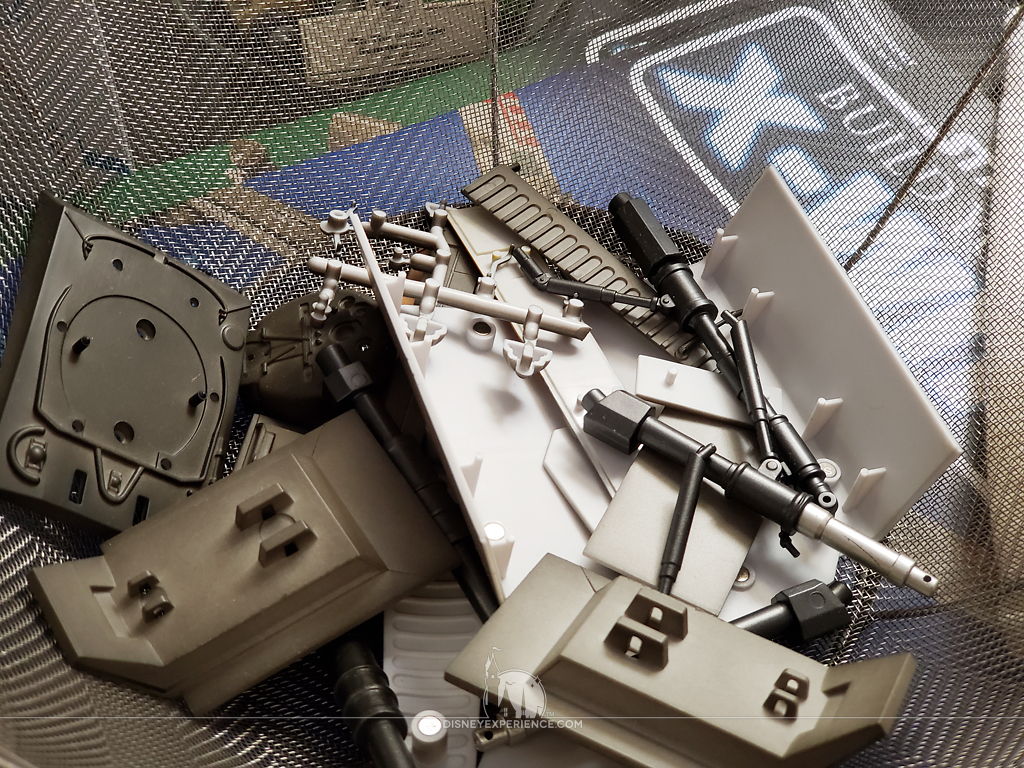
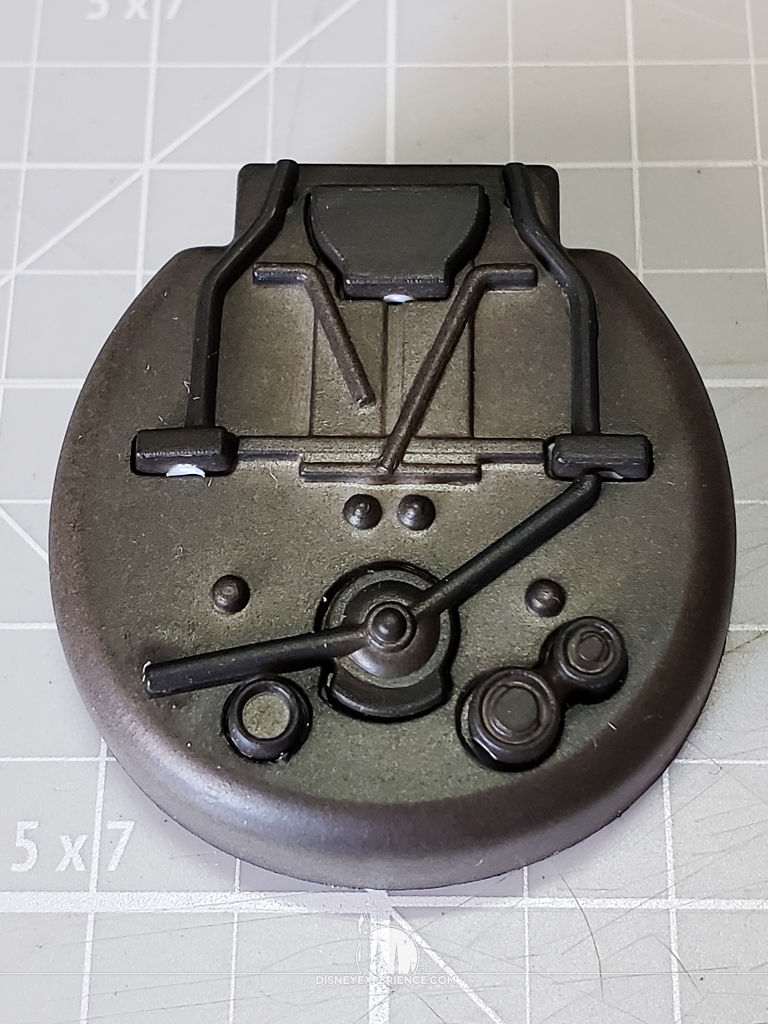
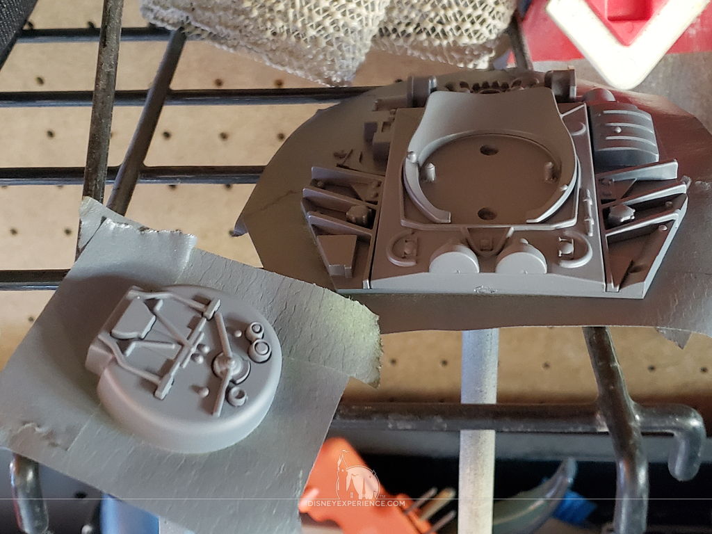
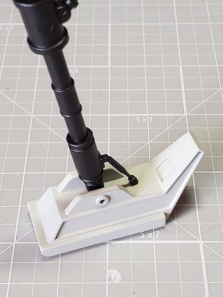
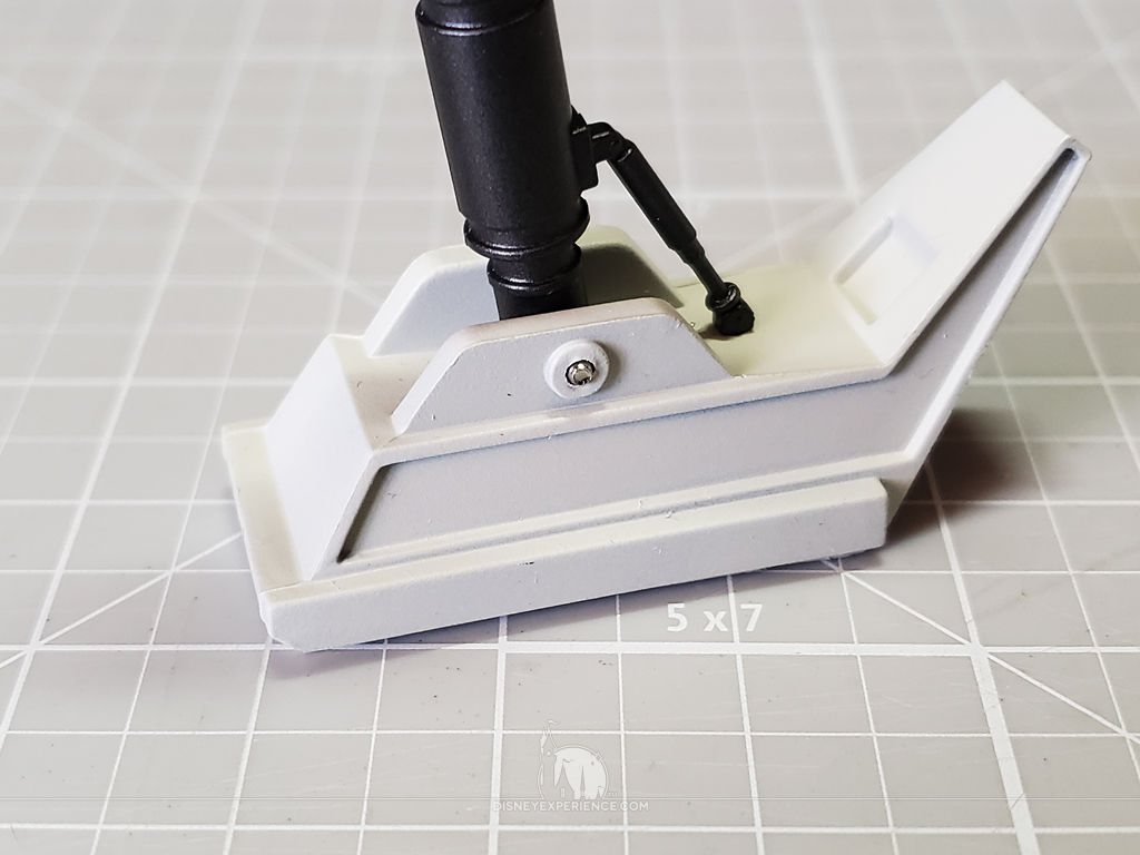
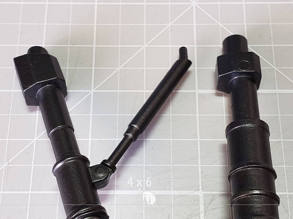
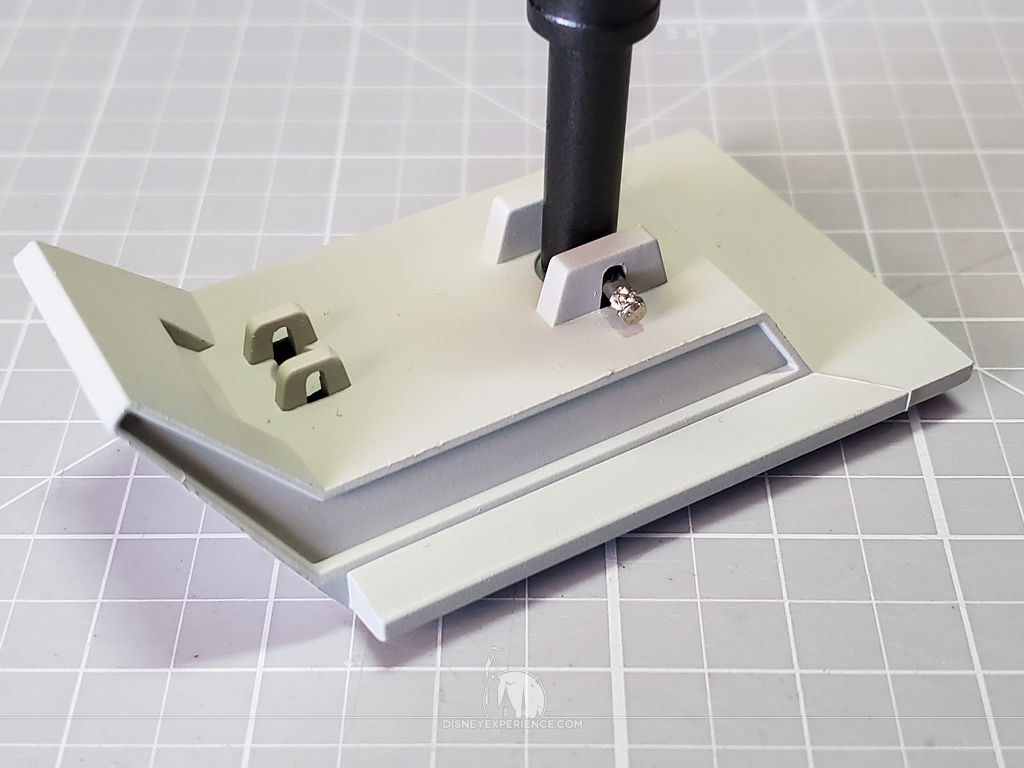
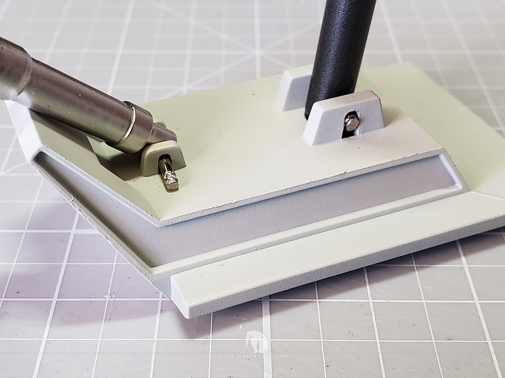
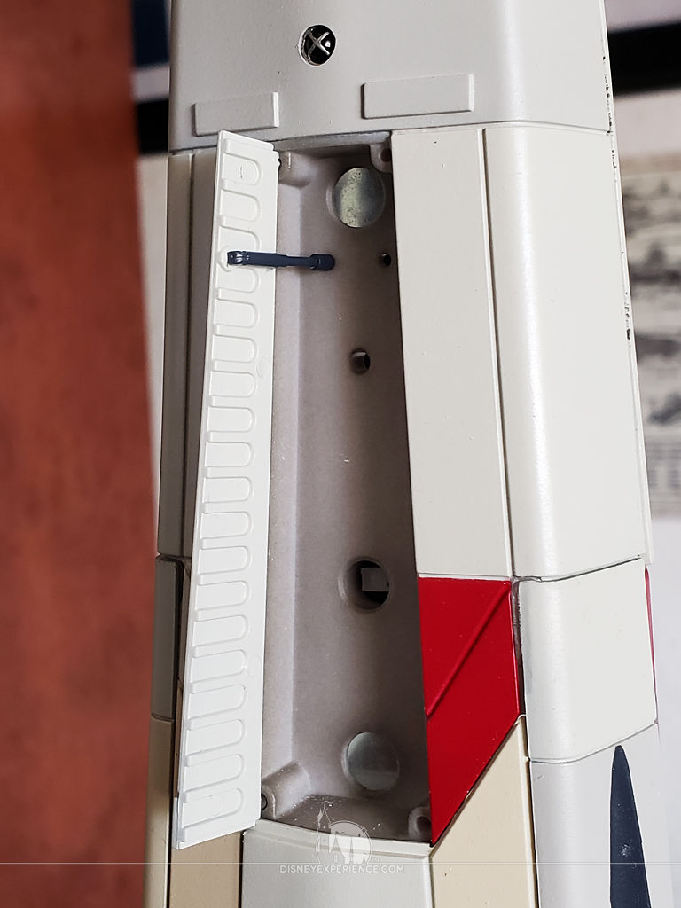
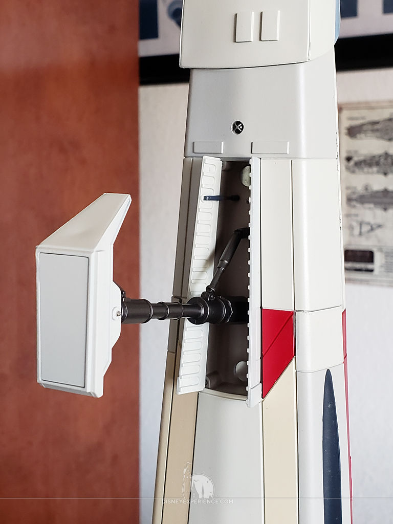
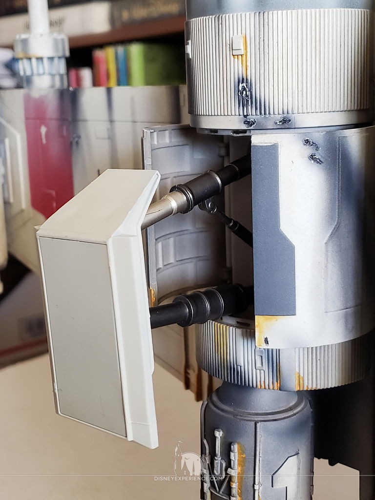
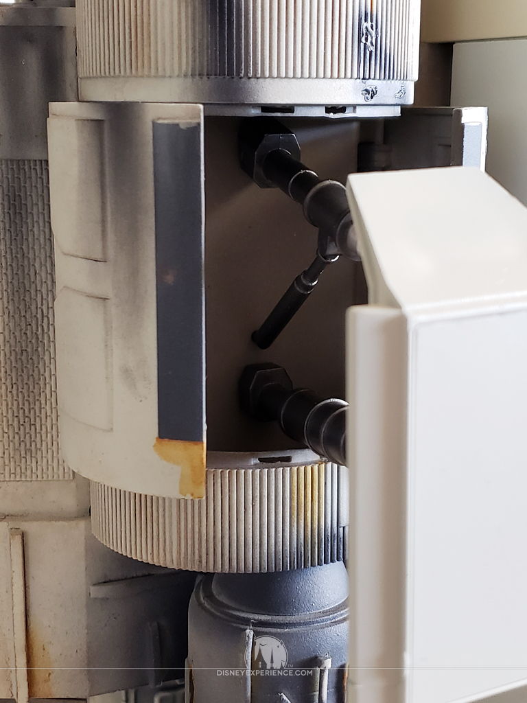
The rear fuselage still needed some detail pieces assembled.
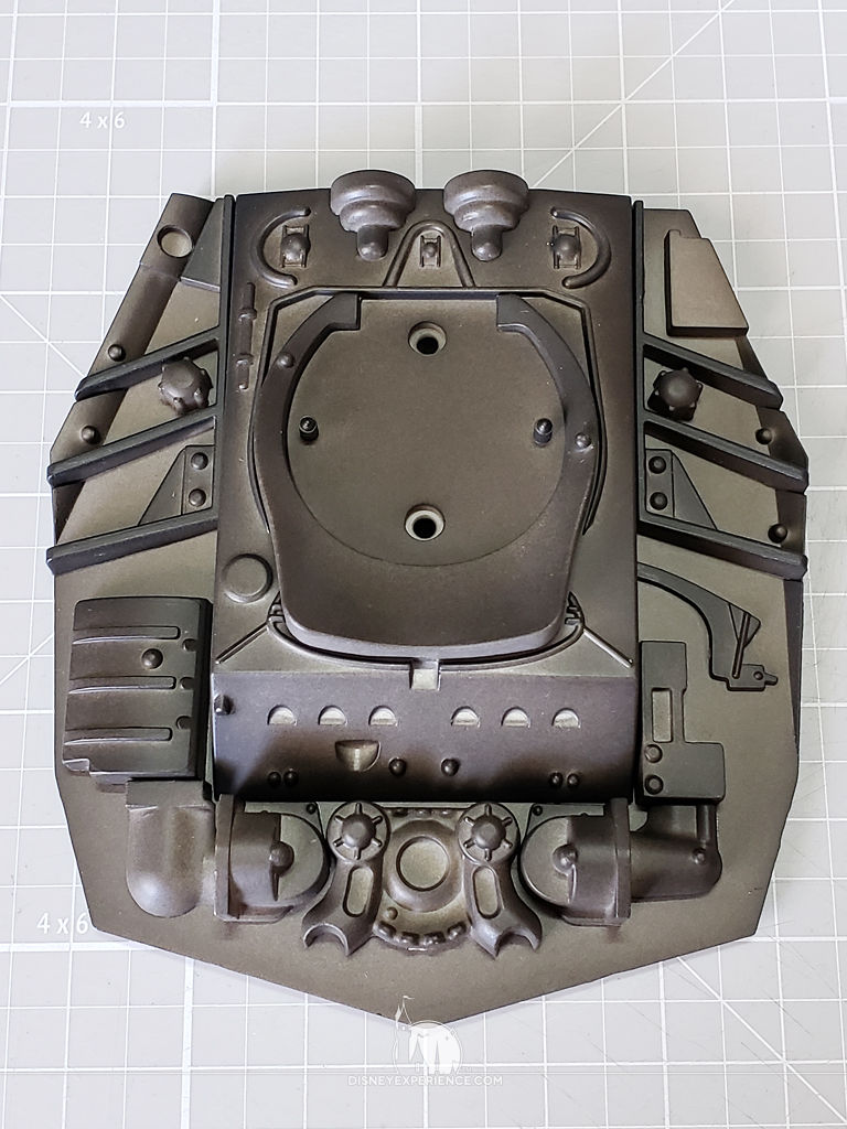
There are two main parts that get greeblies attached to them. They will remain off of the X-Wing until I have both primed and base-painted them.
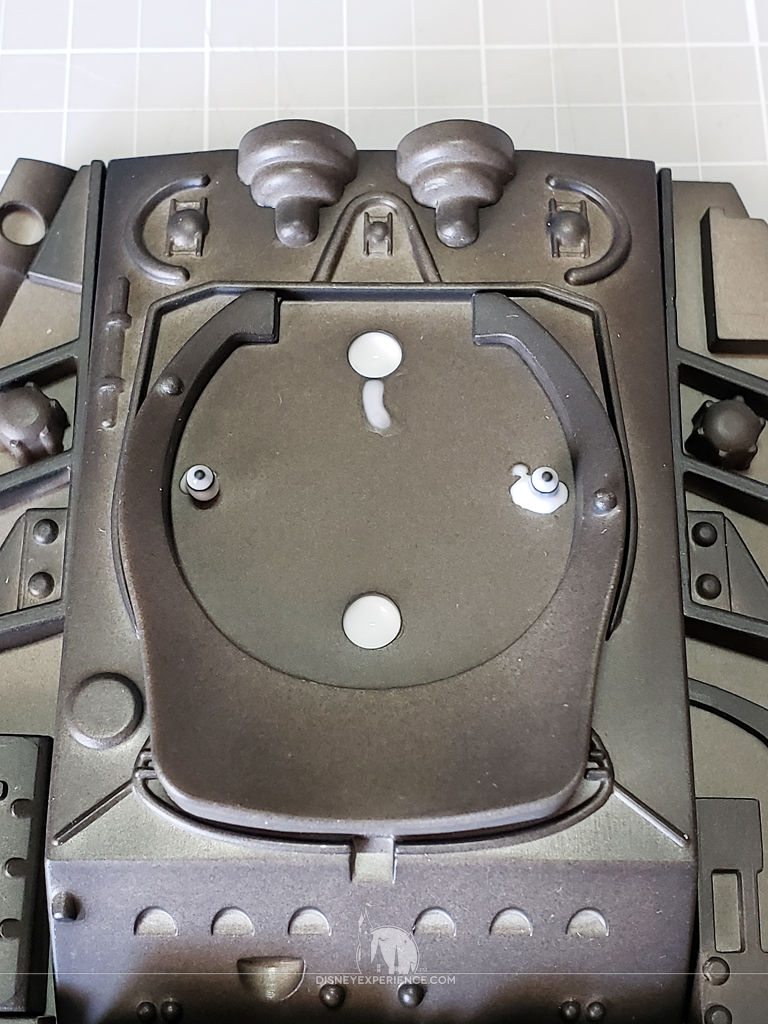
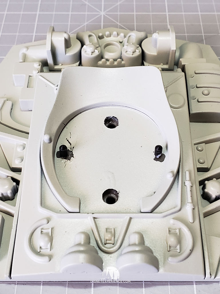
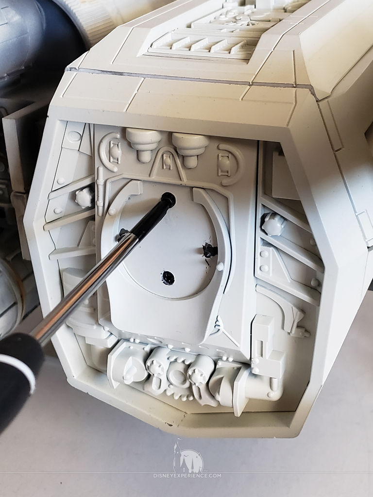
Before priming, I use some Elmer’s Glue-All to mask the screw holes and pegs. In hindsight, I didn’t really need to mask the holes. But, the pegs do need to be masked so that there is a plastic-to-plastic connection for the cement to work later.
I also assembled the three landing feet. Now, I’m ready to prime and paint!
Painting
I suspended the landing feet from metal paperclips that I bent into shape. The feet have convenient holes for hanging.
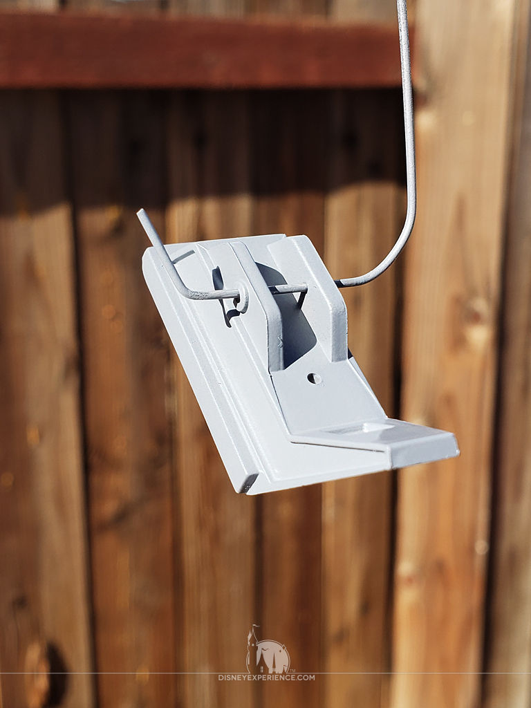
Every part is sprayed with a gray primer, and they are set aside to dry for a day or two.
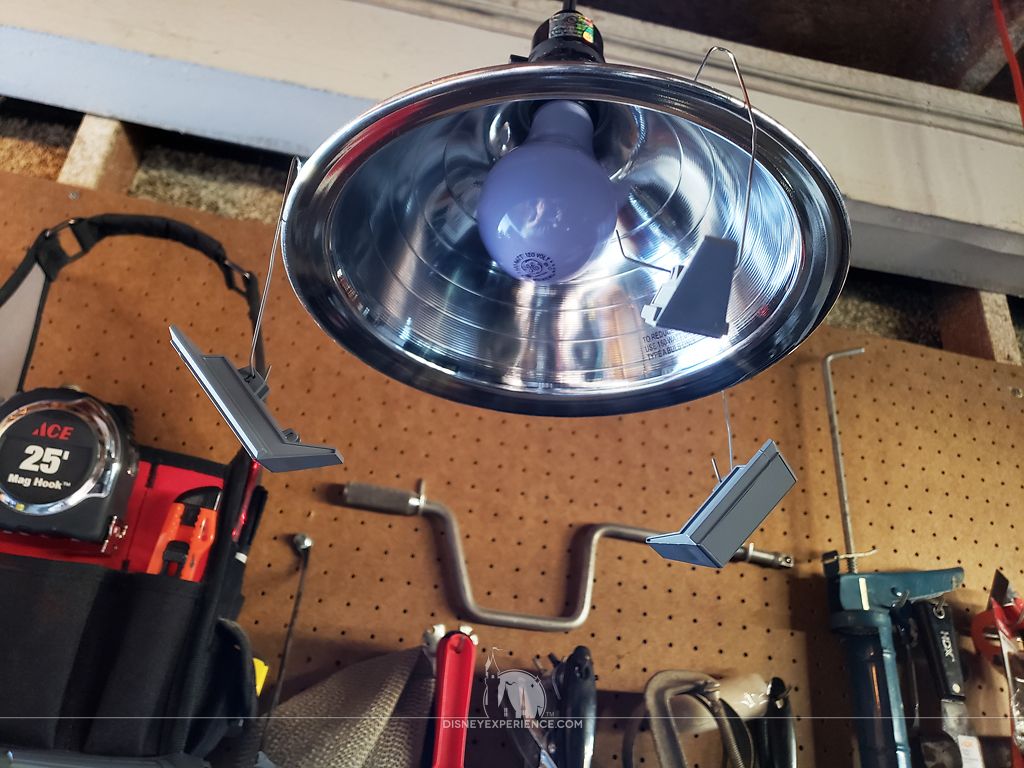
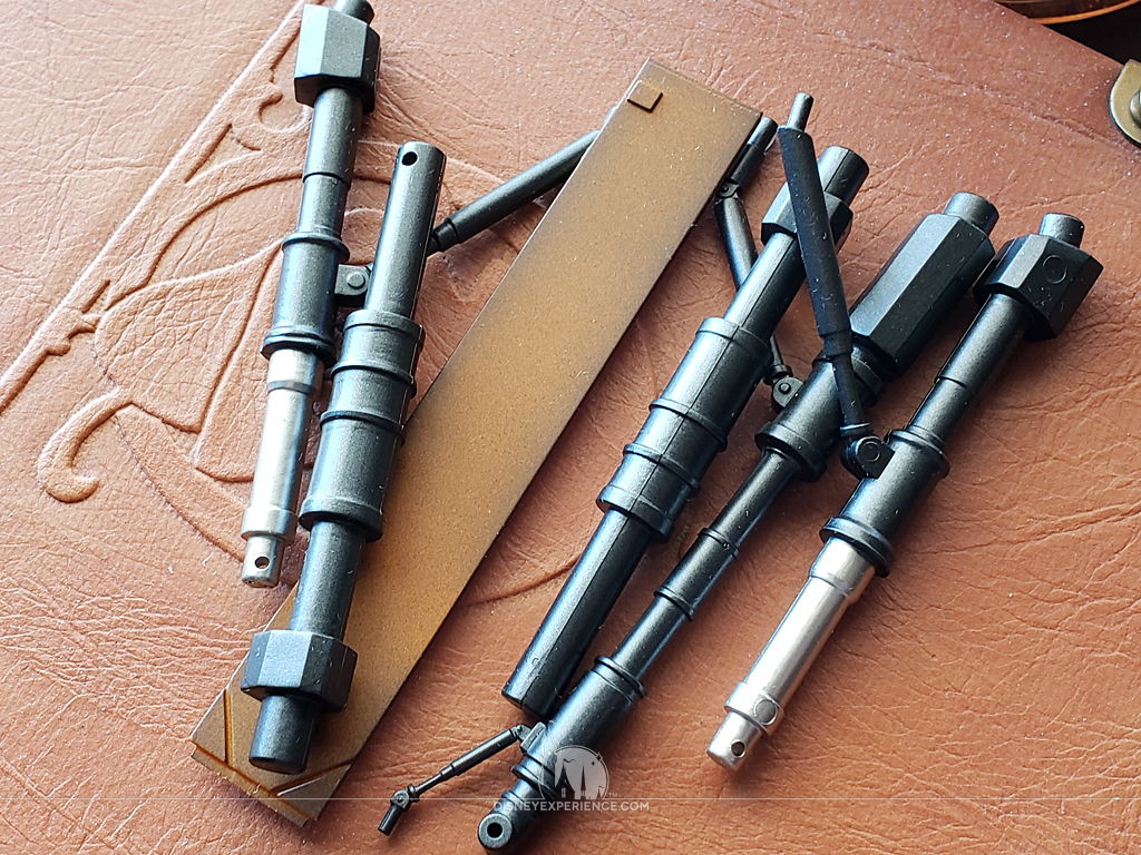
After priming, the parts all get airbrushed a base coat as well as some panel color. Note that the pegs on the landing gear doors were masked before painting. Primer and paint would have made the pegs too thick, and they wouldn’t have fit into the peg holes later.
More Assembly
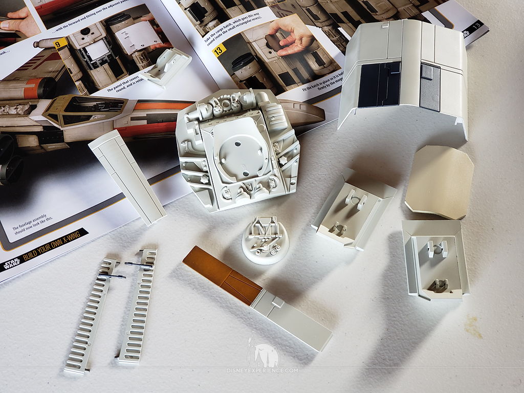
The forward landing gear is a simple attachment. The peg goes into the small hole, and the leg is held in place with a small, friction-fit pin.
The two rear landing gears each have two legs. The rear leg fits just fine with the friction-fit pin.
The forward leg, however, will need some super glue to hold the pin into place so that it doesn’t slip out. Now, let’s fit some panels!
The battery box cover snaps on easily with magnets. It’s a firm connection, but it’s still easy to remove by hand.
The switch cover could use stronger magnets, but it works.
Conversely, the forward landing gear cover could use weaker magnets. It snaps in well, but it can be tricky to get it back out.
When the forward landing gear plate is removed, the two landing gear doors plug into holes, friction holding them securely in place. Likewise, the landing gear is also held in place with friction.
The rear landing gears are a little trickier to plug in. They are a snug fit, and they don’t always want to cooperate.
With the landing gear in place, I can now stand the X-Wing on its own feet, which makes the rest of the build a lot easier.
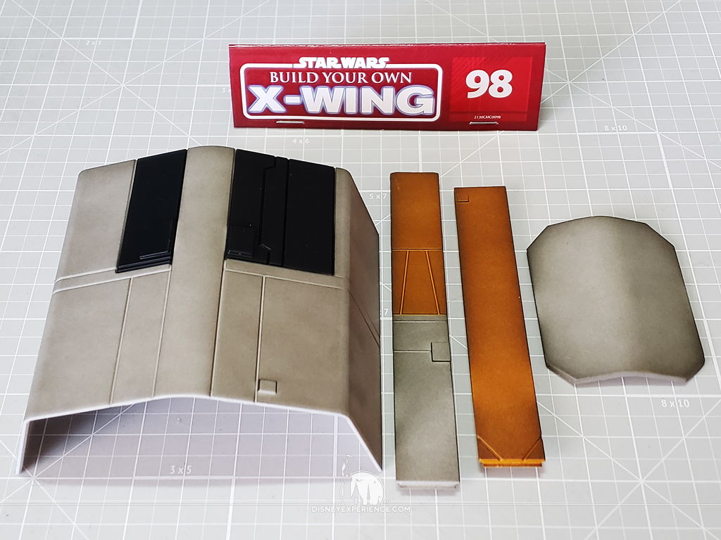
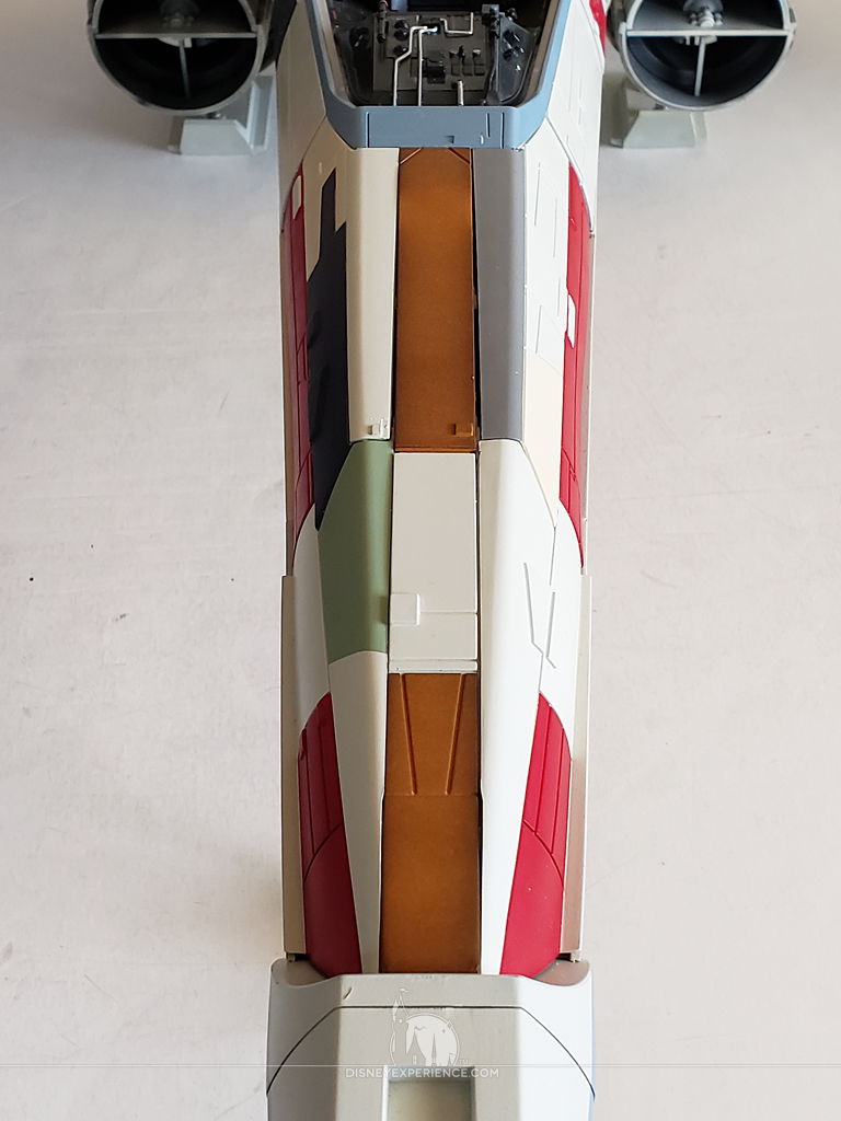
The nose section gets its final two plates installed.
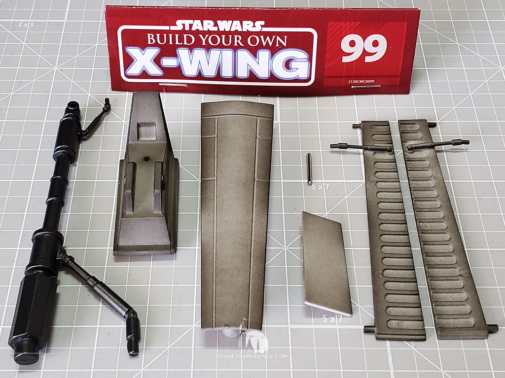
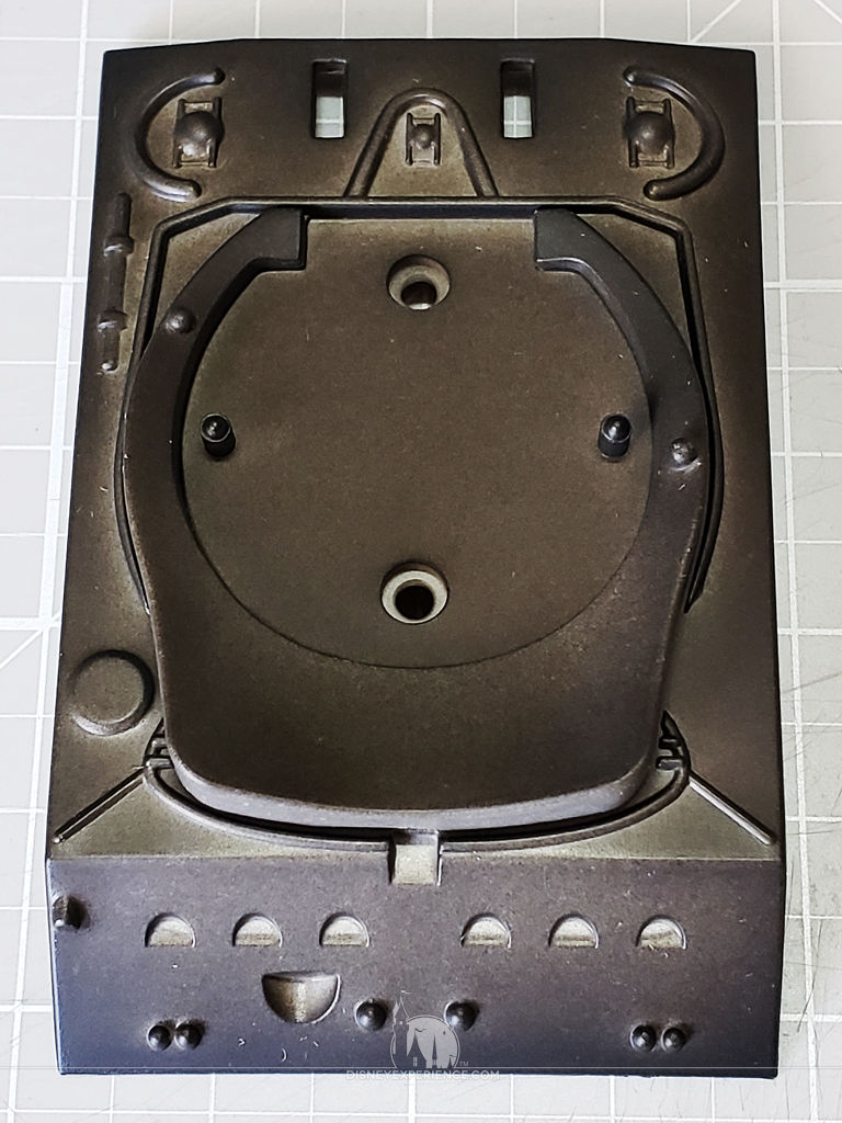
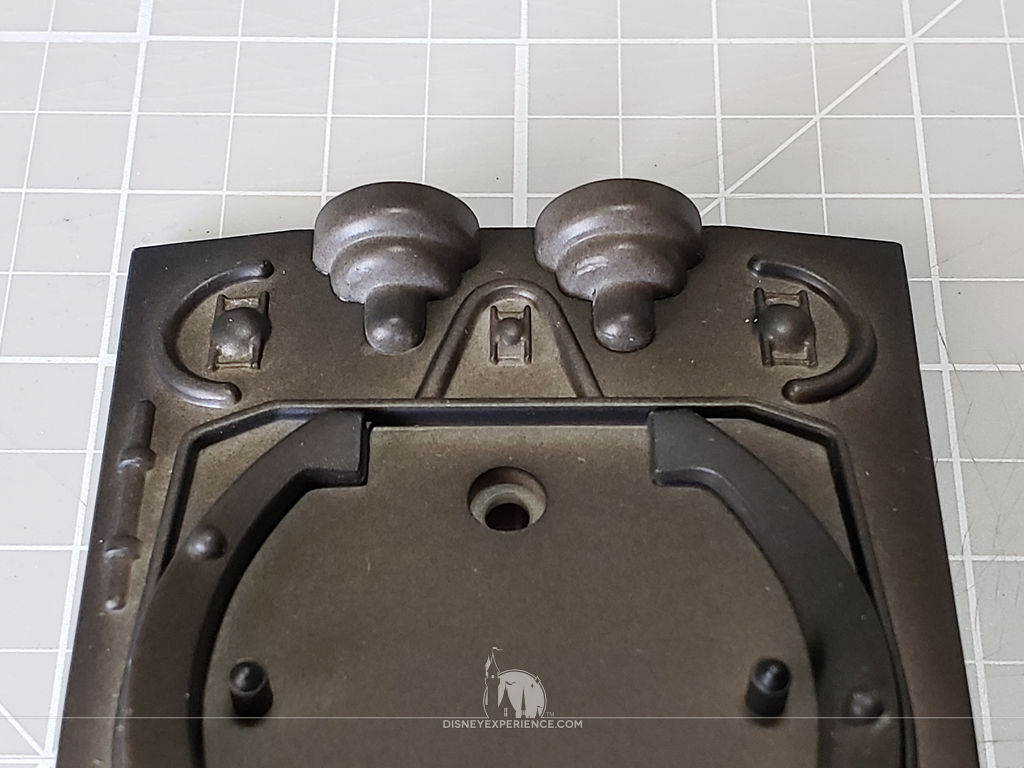
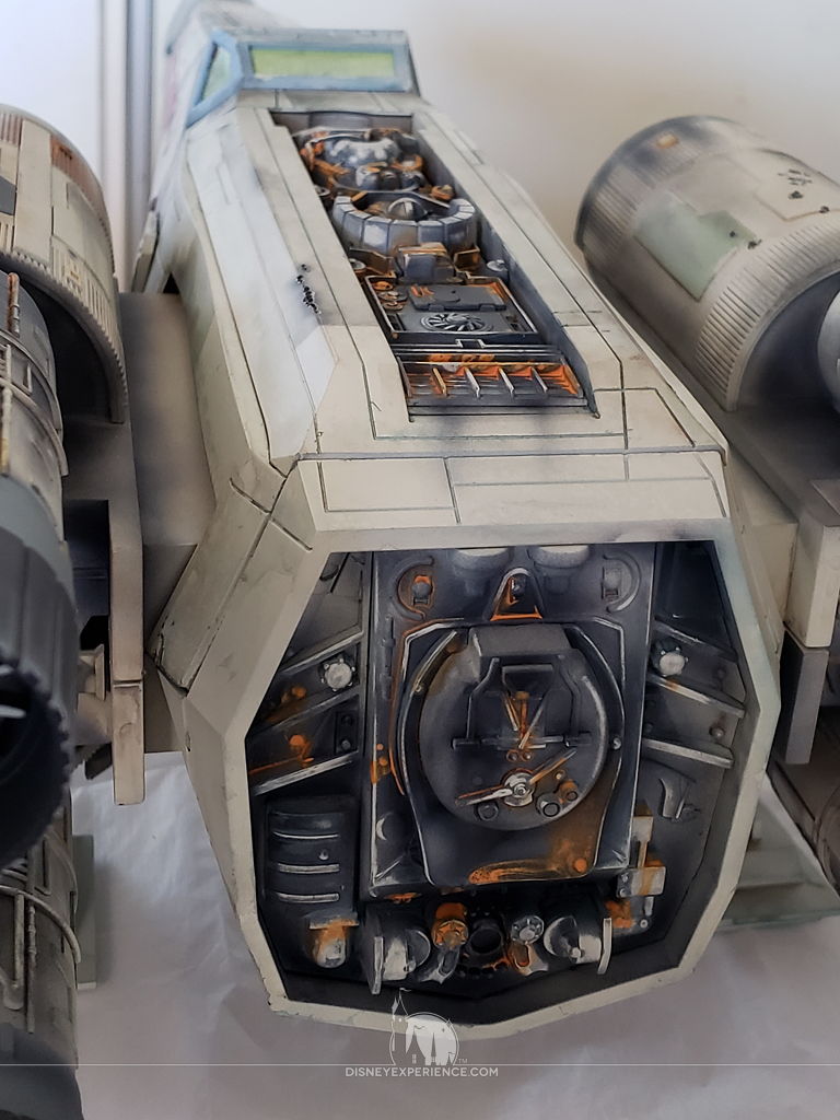
The glue is removed from the rear fuselage pieces. Since it has been a couple of days, the glue is very hard, and it takes some force to pry it all off. I don’t have to worry about being too careful since the second rear fuselage piece will cover up any damage.
The large piece is screwed into place . . .
. . . and the smaller piece is cemented into place.
Weathering
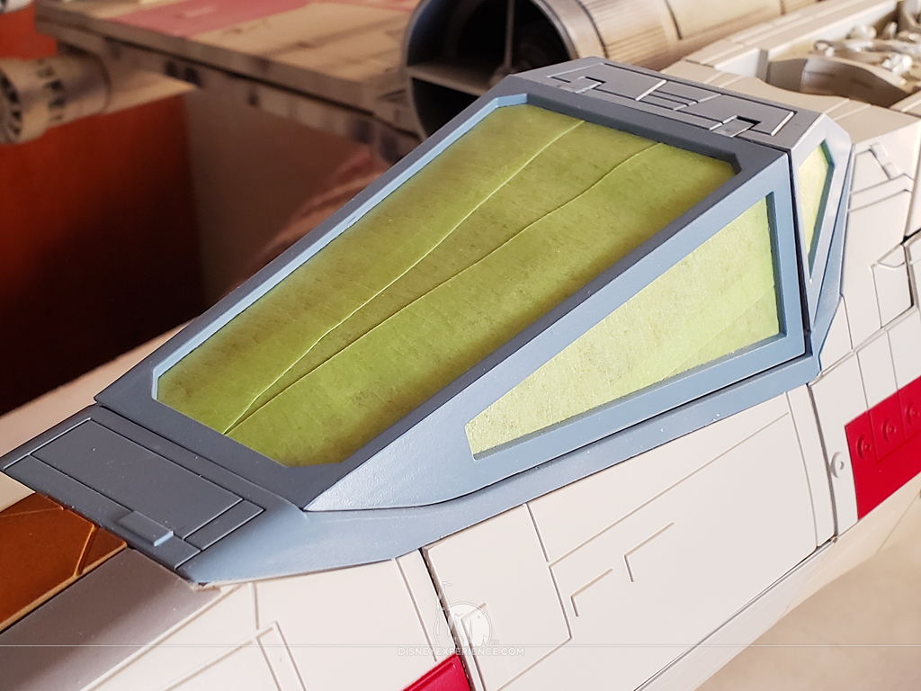
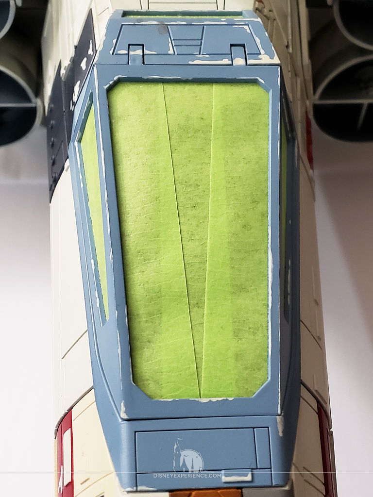
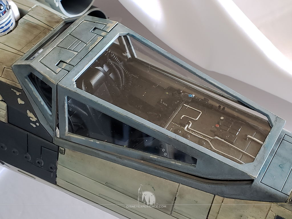
The cockpit canopy is masked with tape on the inside with tape and dry-fitted into place on the X-Wing. This will keep the paint from getting all over the interior. Later, the canopy will be removed to receive its windows.
I also used a piece of tape to carefully mask the remote sensor underneath the nose. And, since I will be using a lot of water, I removed the batteries to prevent any possible short circuits in the future.
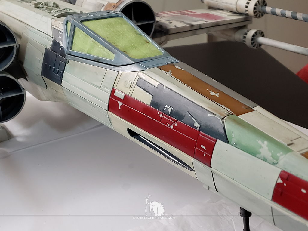
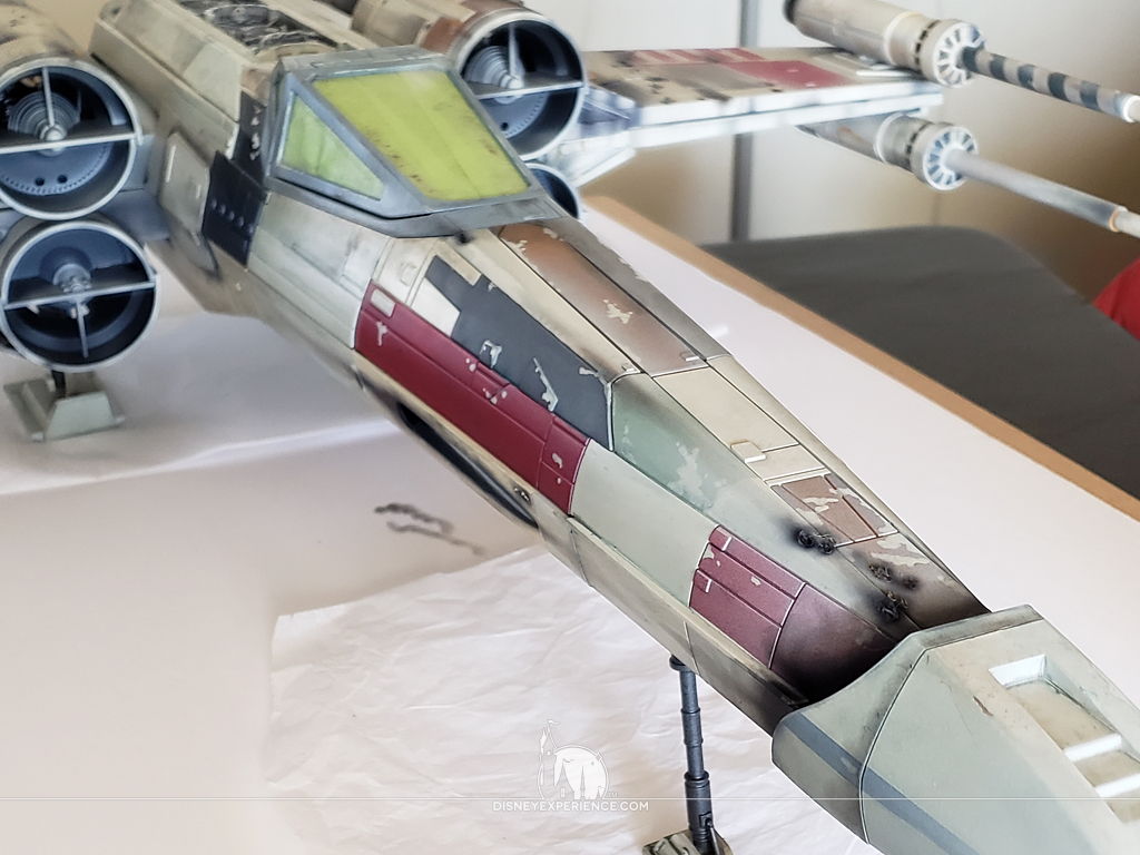
I simulate paint chipping by painting on some of the base color over the colored panels. The same is done for the canopy.
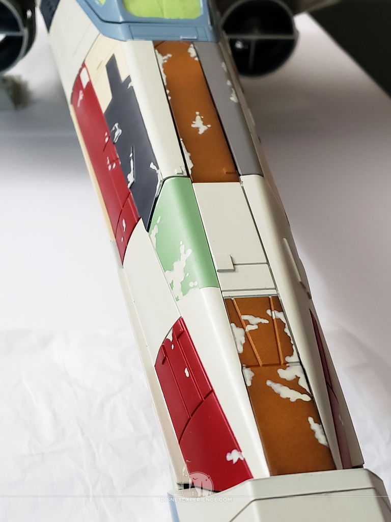
To simulate dirt and muck, I speckle the body with gray, brown, and dark blue paint. A few mist sprays of water from a spray bottle keeps the paint from drying. Then, I use a wet, wide paint brush to smear it horizontally.
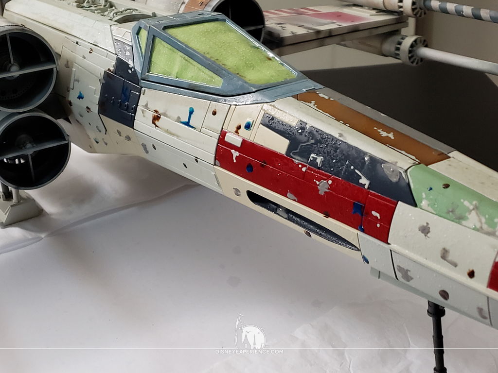
The result is some lovely grime.
The excessive use of water will mean that I cannot install the batteries for several days. Wet electronics usually function normally after being wet so long as they are completely dry before running electricity through them. I don’t know if water got into any of the electronics (I didn’t use THAT much water), but it doesn’t hurt to be cautious.
After the grime layer, I simulated dust and fading by lightly spraying areas with the X-Wing’s base color. Then, I used Tamiya Weathering Master B to add soot to the hull.
Next, I airbrush a heavier dose of soot/oil/grease on the top and rear fuselage sections.
Using Tamiya Weathering Master C, I apply orange rust. I like to use a paint brush dipped in isopropyl alcohol to apply it.
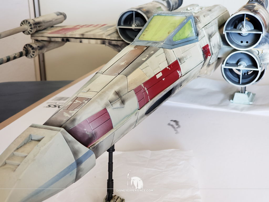
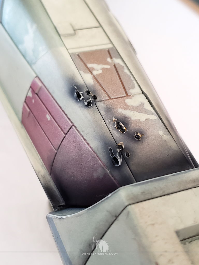
Blaster damage is created by melting the plastic with the pointy tip of a wood burning tool. Melting the plastic is SO fun and relaxing!
The blaster marks are airbrushed with some dark accents, and I also take this time to enhance any soot that needs to be a little darker.
I use a sharp chisel blade to carefully slice off the excess plastic that came from the melting process. This exposes the light plastic around the edges of the blaster marks, making them more realistic.
After all of the painting and weathering are completed, I apply a couple coats of gloss varnish as a protective under-layer. After that, I apply two coats of matte varnish for a nice, dull appearance.
Gloss varnish dries as a hard shell, so it’s good for protecting against scratches and scrapes. Matter varnish is much softer, and it doesn’t protect very well.
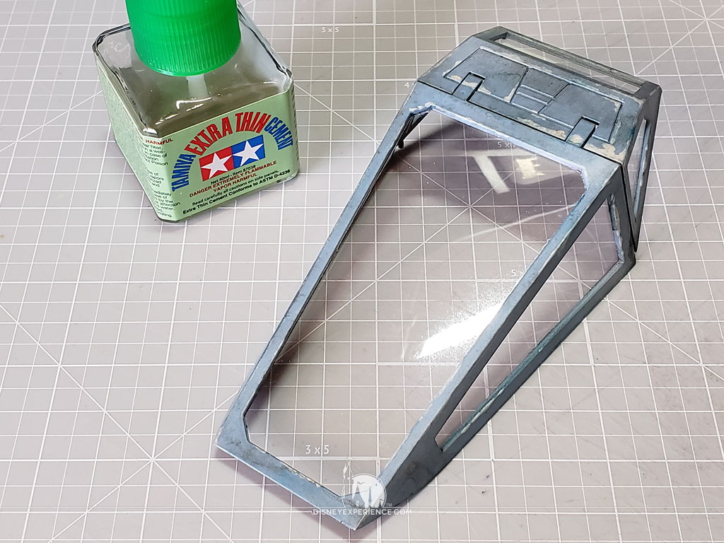
Canopy Windows
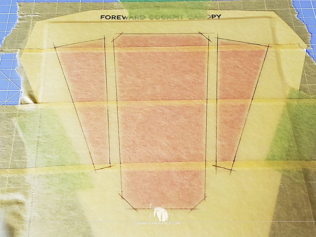
I created window templates for the canopy, printed them out, and taped them to a cutting mat.
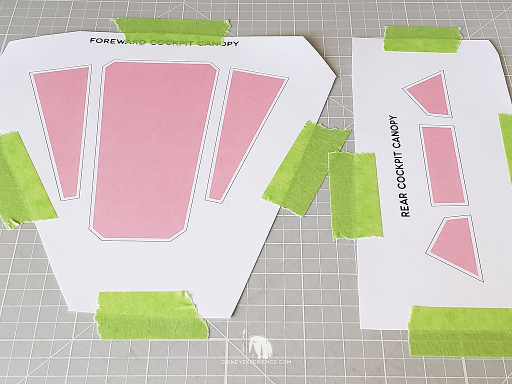
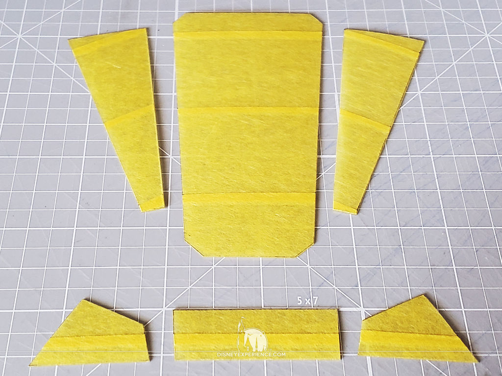
I taped a piece of K&S clear plastic sheeting over the templates using Delicate Surface FrogTape, which is a little transparent. I trace the window shapes directly onto the FrogTape, and I cut the pieces out.
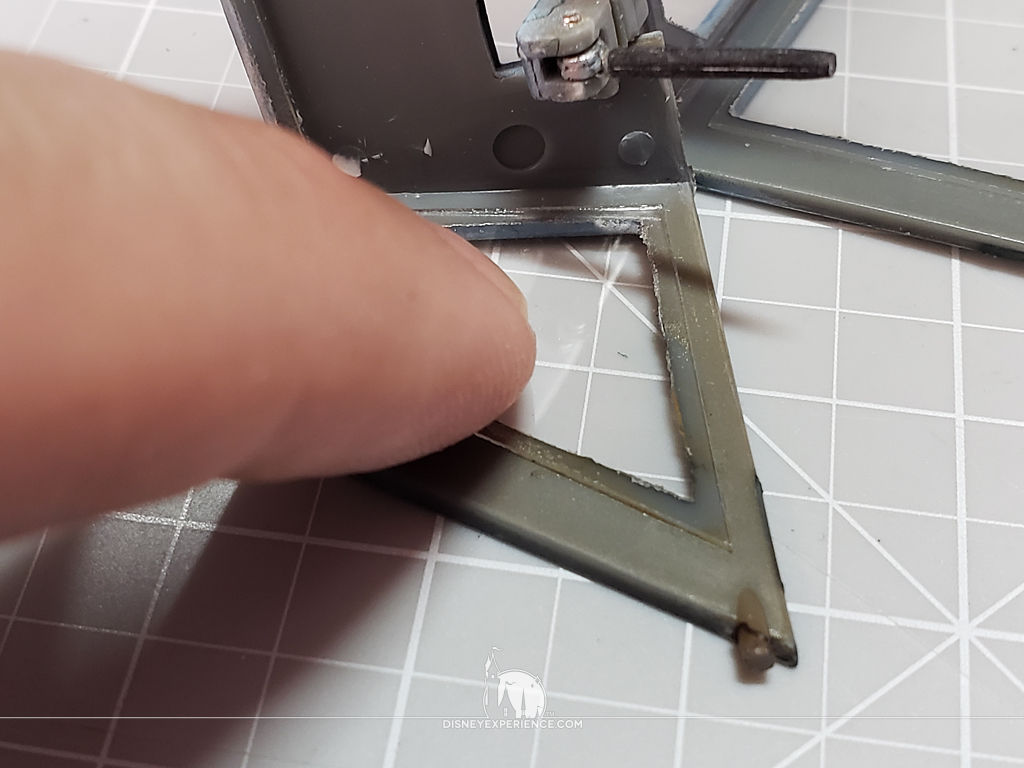
Each window (glazing) is attached to the inside of the canopy with Tamiya Extra Thin Cement. Gentle pressure is needed to hold the windows down as the two plastics bond. Too much pressure, and the cement can create a spider-web/cracking effect.
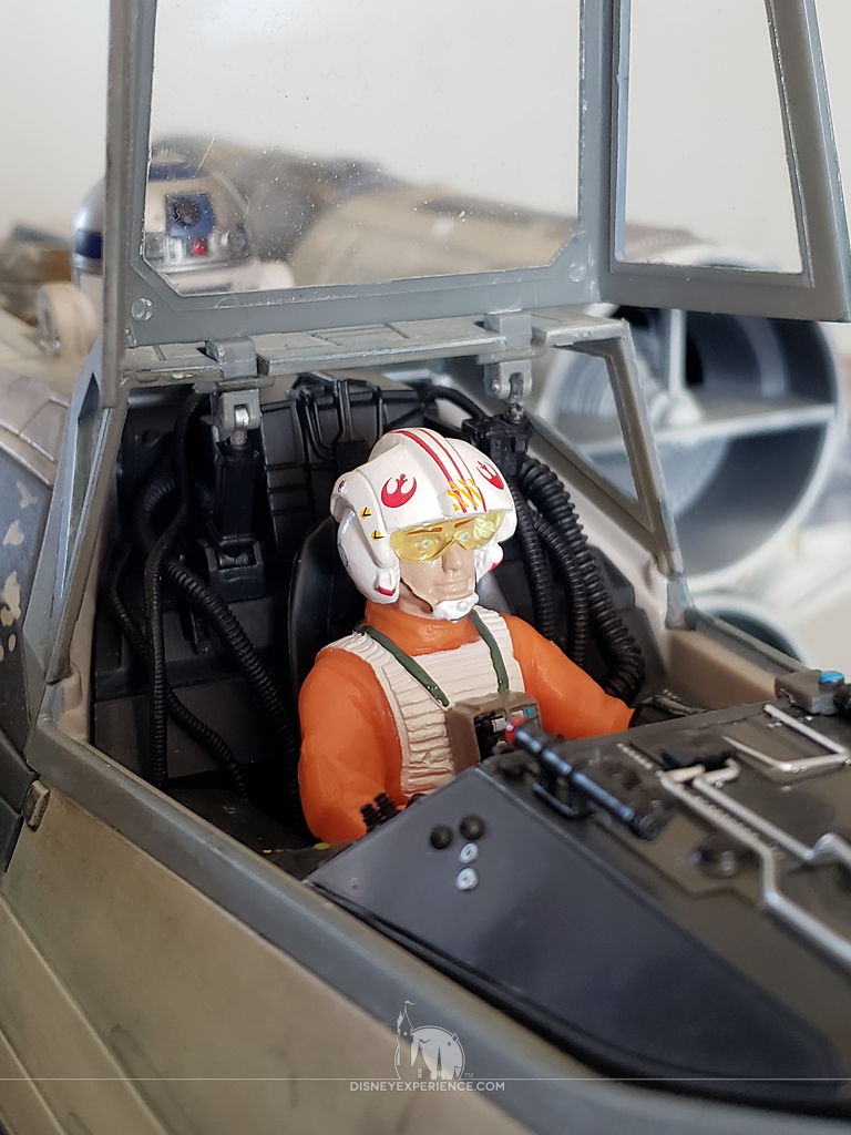
When the windows are in place, the canopy can finally be glued to the cockpit.
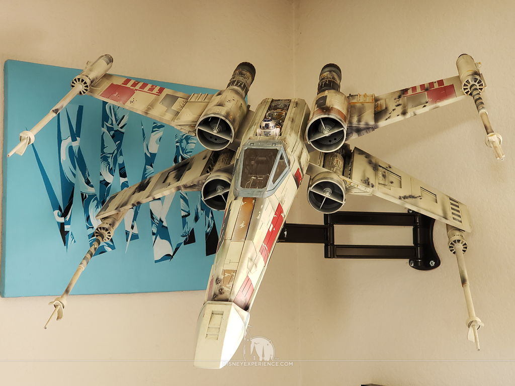
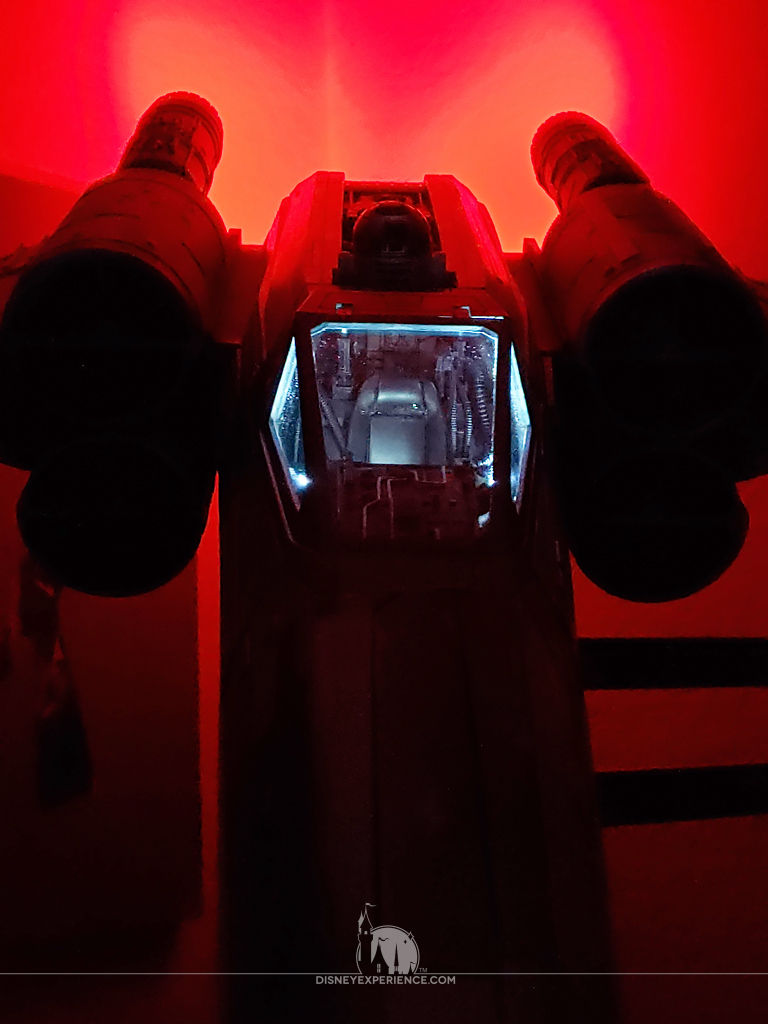
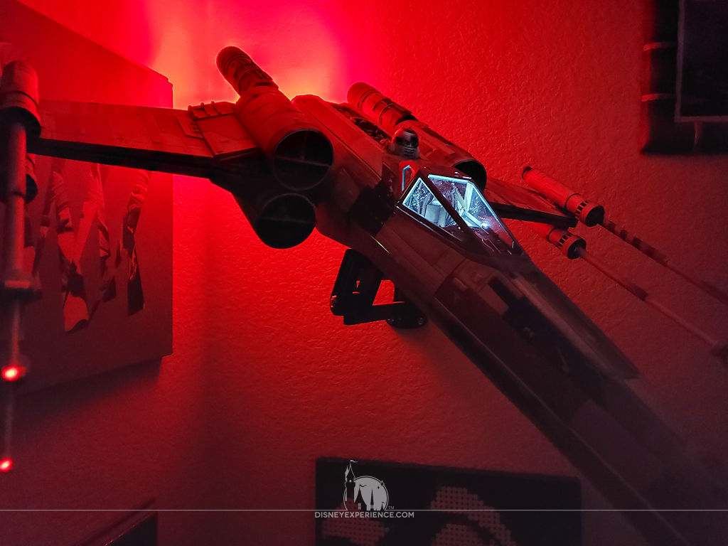
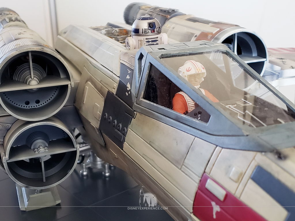
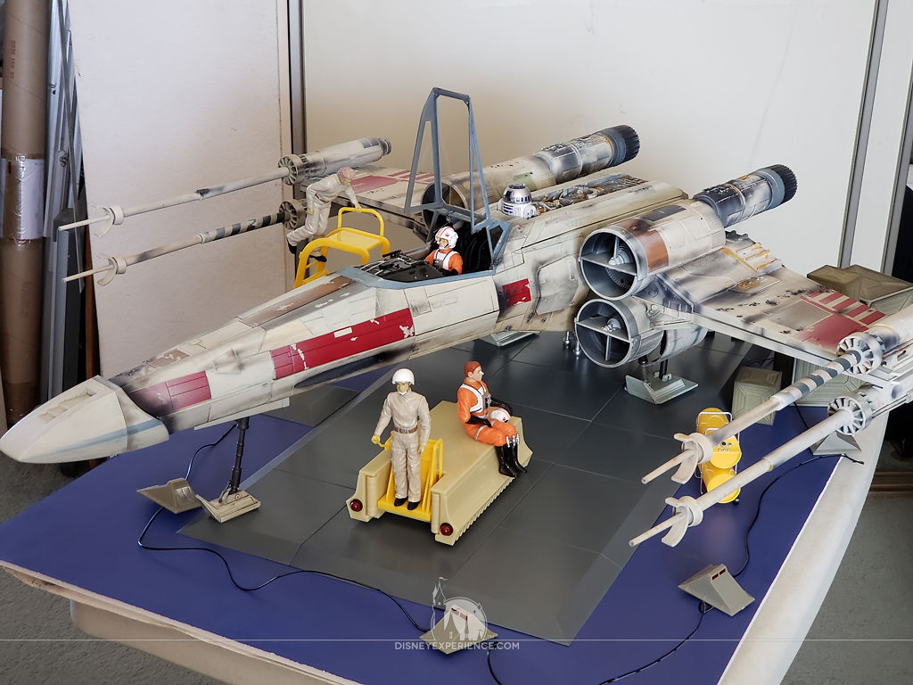
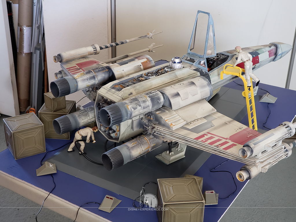
The X-Wing is now complete, so it goes back onto its stand for permanent display.
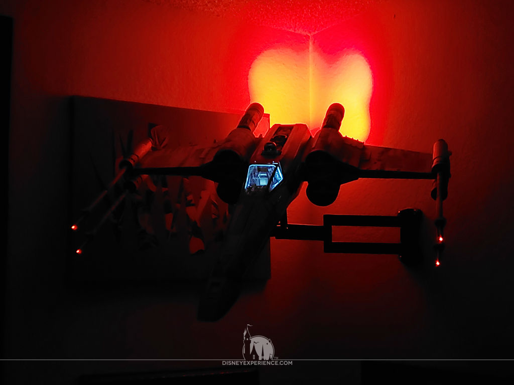
Of course, the lights all have to be tested.
Premium Subscription Diorama Set
The diorama set that came with my premium subscription arrived about a week after my last subscription box was delivered. Everything was packed into a single large box, which seemed a bit too big for what was supposed to come with the diorama set.
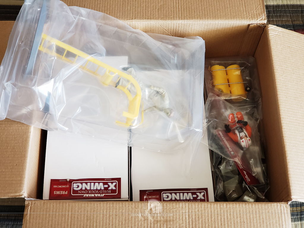
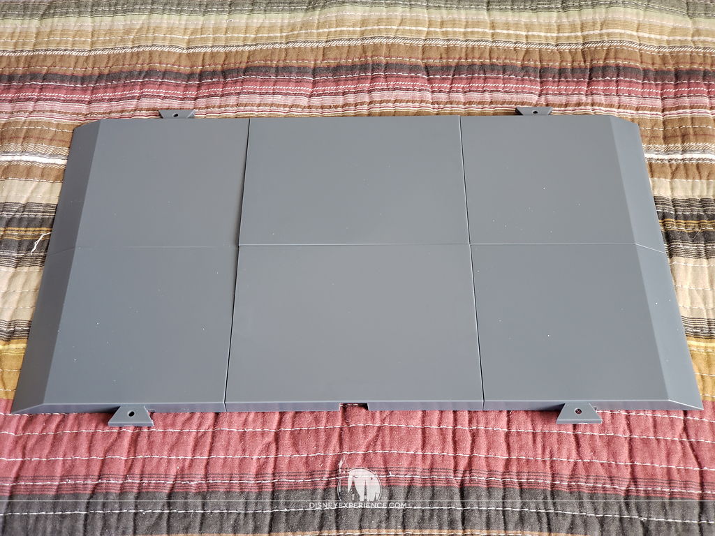
After unpacking everything, it was clear why the box was so large. Plates were included with the set. Plates that were never advertised in any of the images or text on the Model Space website. The plates connect to create a platform.
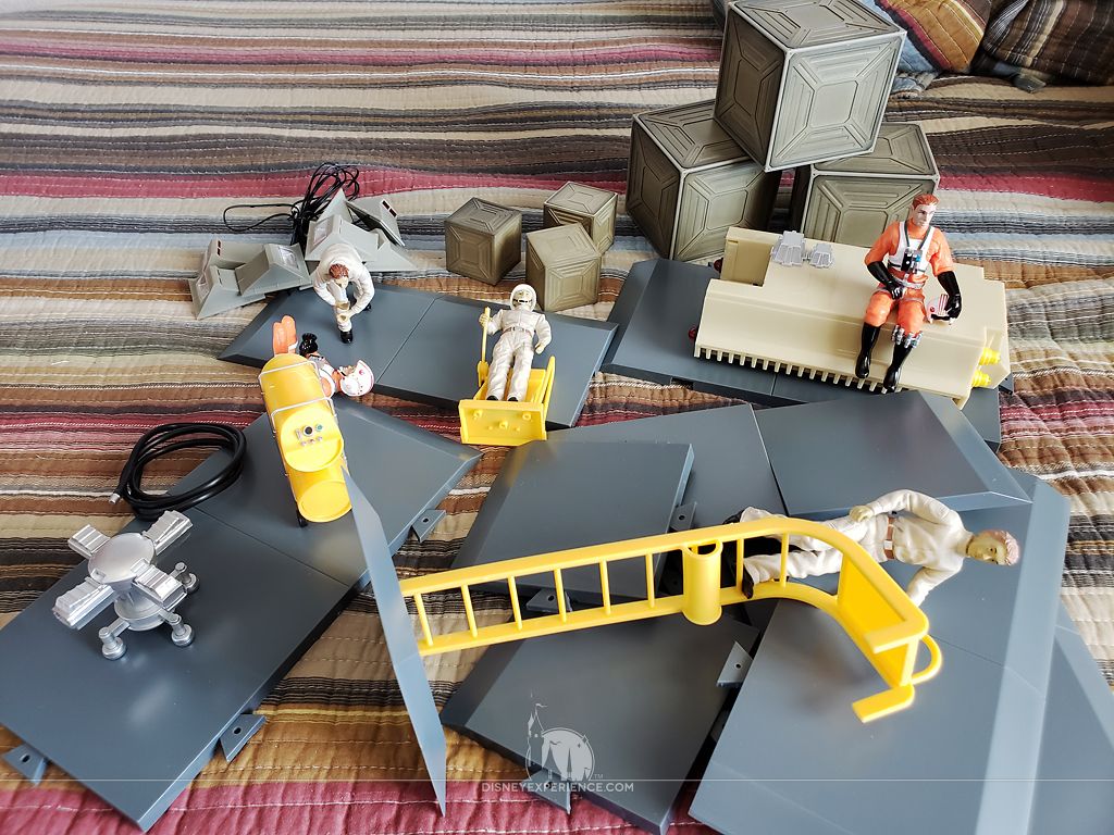
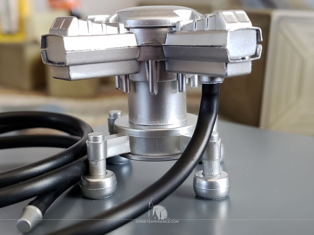
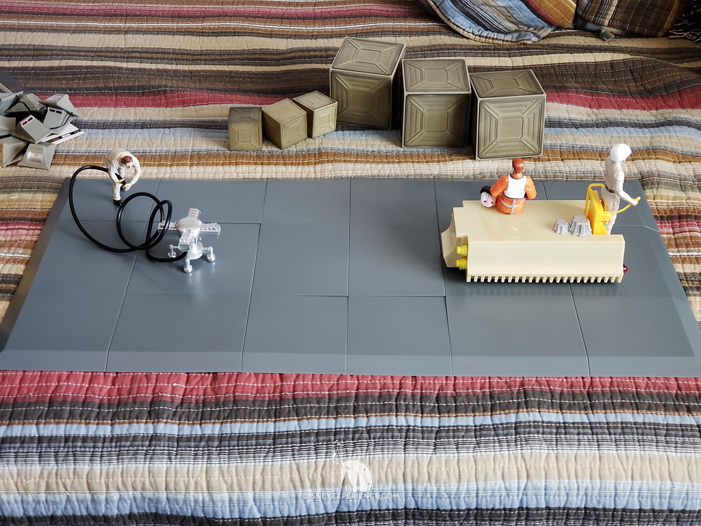
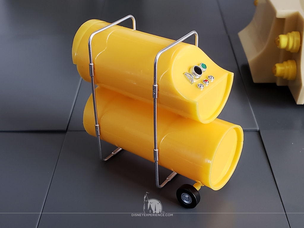
The transport, fueling thing-a-ma-jig (highly technical term), fuel person, and cockpit ladder are all attached to plate pieces. This is very disappointing as that means that they have a fixed location; I cannot position them to my liking. I could cut everything free, which would solve several problems.
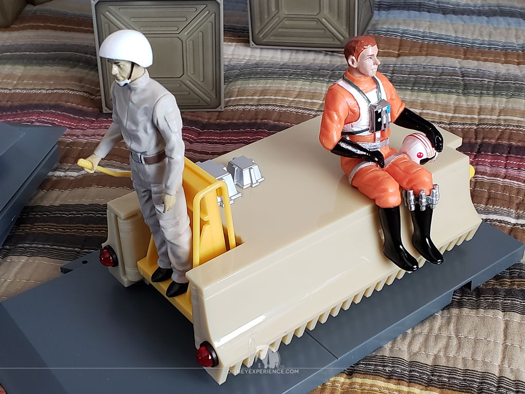
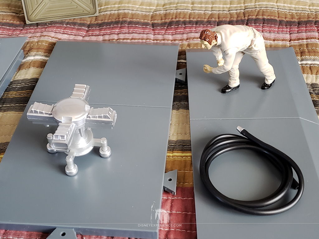

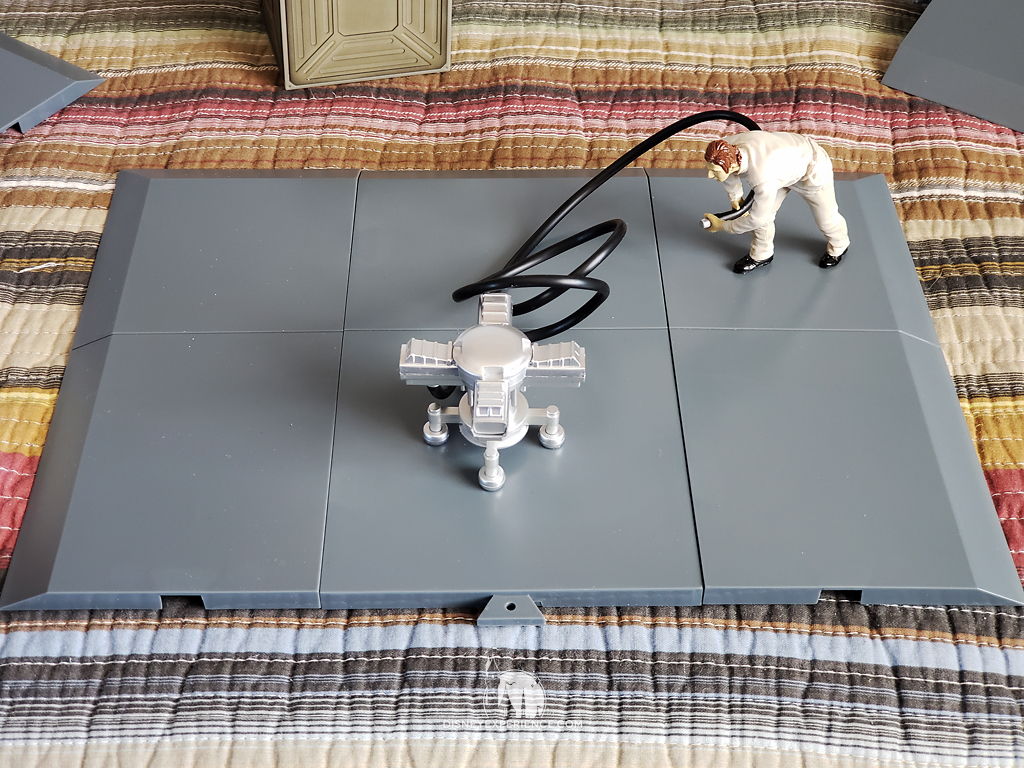
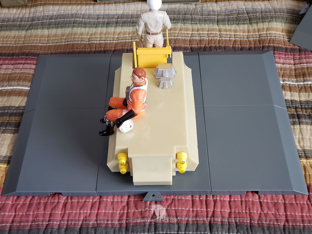
Assembling the plates was confusing. There are absolutely no instructions, and they are not shown in any of the X-Wing images (not even in the magazines), so I had no reference. When complete, the base is uncomfortably small for the X-Wing. The base is just big enough to fit the landing legs, and the figures are just barely in positions to allow room for the X-Wing body.
The figures are horribly painted, screaming for a repaint—which I recommend. I won’t be using my diorama set—my X-Wing is wall-mounted—so I won’t be painting mine.
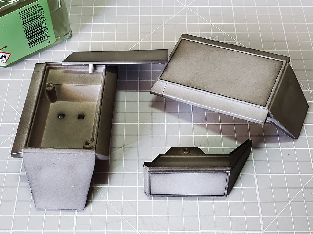
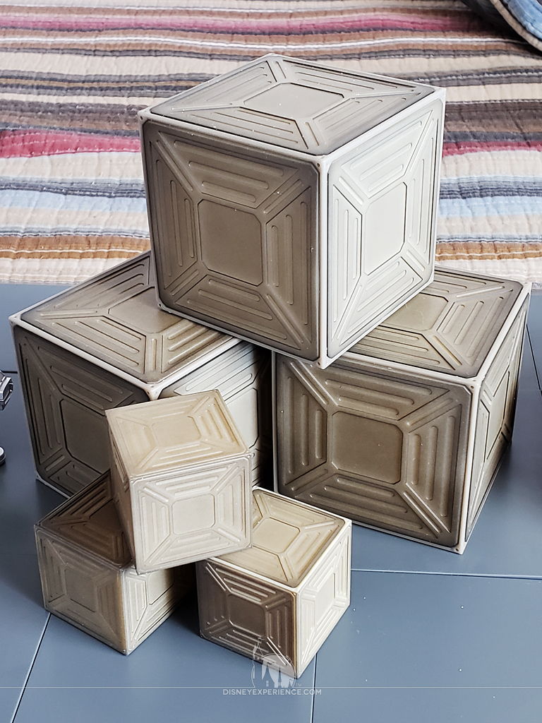
The cargo boxes are one of the neater accessories. They’re large and have a neat design that screams “Star Wars.”
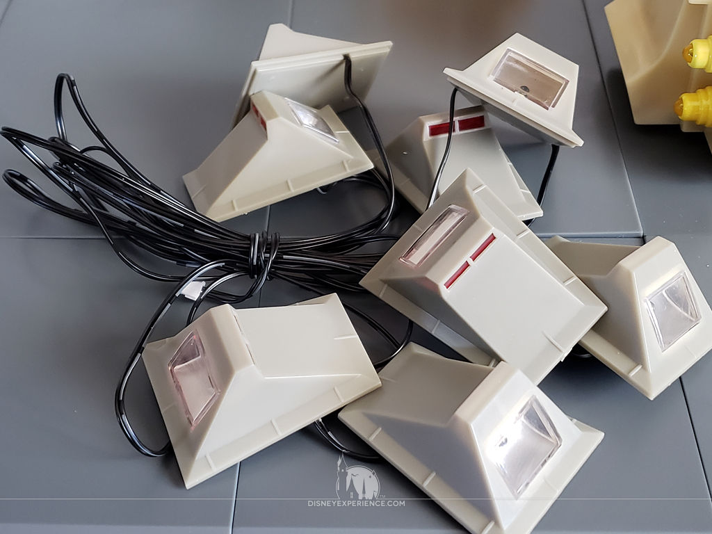
The lights were another confusing item as there was no power supply within the box. I looked at advertising photos, but the power source for the lights was always either hidden out of frame or behind the included cargo boxes. Well, it turns out that I am supposed to use the battery tester that came with the first few issues of the subscription. This was never mentioned in any of the magazine issues.
I tossed mine out about a month ago thinking that I would no longer need it. It was only a tester, after all, and the X-Wing has two sources of power: batteries and a USB power cable. Plus, I assumed that the landing lights would have a proper battery pack with an on/off switch.
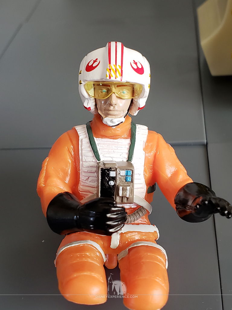
The Luke Skywalker figure has no legs, which is fine since they can’t be seen anyway. This is the only item that I will be using as part of my display.
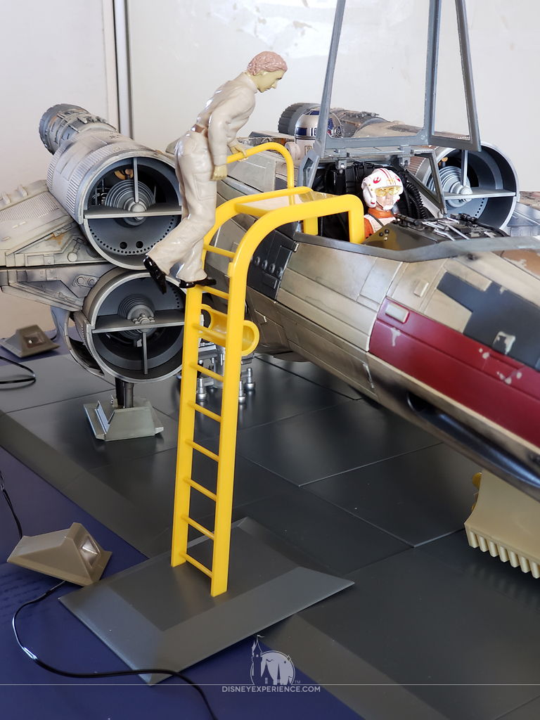
The ladder’s base doesn’t work well with the X-Wing base. The ladder is either too far from the X-Wing, or . . .
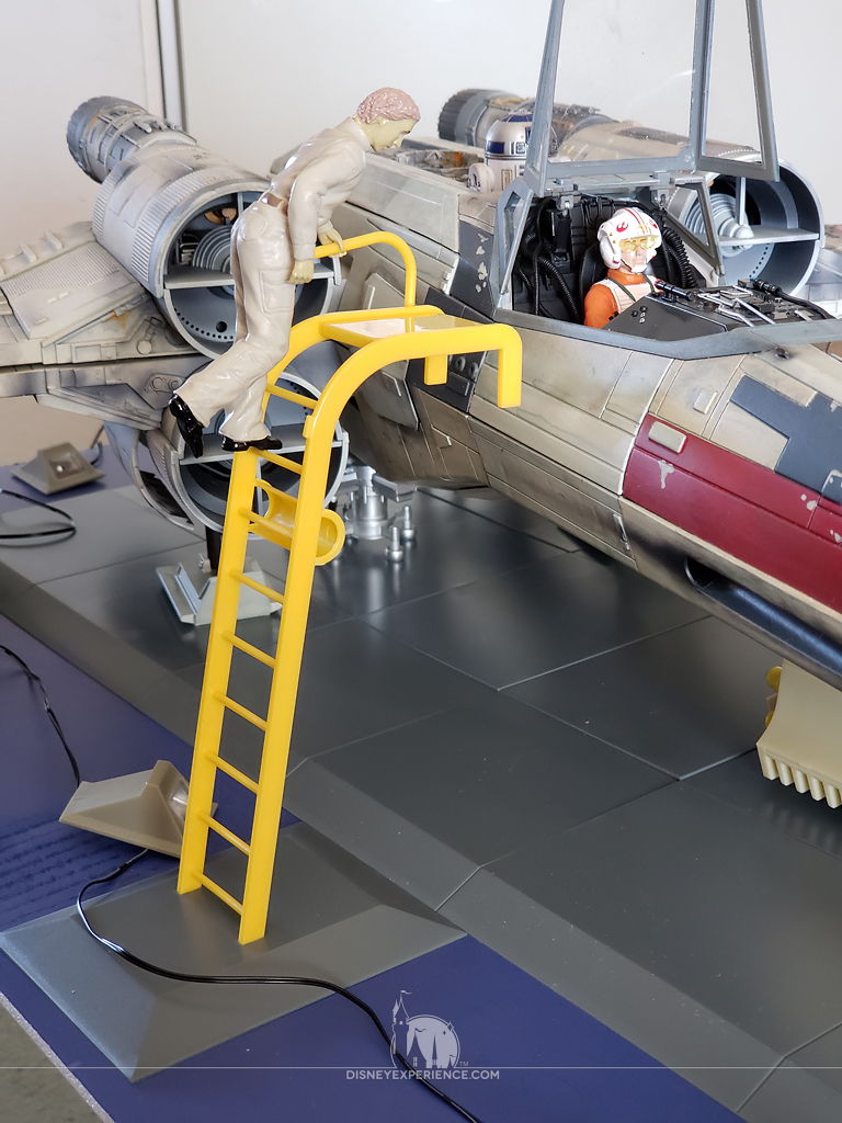
. . . it awkwardly overlaps the diorama base when properly hooked into the cockpit. The ladder is definitely one item that definitely needs to be cut free from the diorama base.
As I mentioned before, the diorama base is only just big enough for the X-wing to fit. It would be better if the figures were not permanently mounted to the diorama base. Display options are limited.
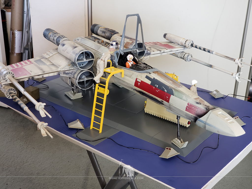
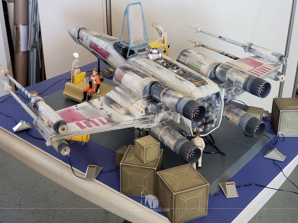
Ultimately, I don’t think the diorama is worth the extra money. At least, it wasn’t for me.
Both the post author and this website have not received any compensation for writing this post. Both the post author and this website have no material connection to the third-party brands, products, or services that have been mentioned. Some of the links in the post above are “affiliate links.” This means that if you purchase the item, we will receive a commission. As an Amazon associate, we earn from qualifying products. This is being disclosed in accordance with the Federal Trade Commission’s 16 CFR, Part 255: “Guides Concerning the Use of Endorsements and Testimonials in Advertising.”
Hioved your journal you know your stuff. Can you help me. Got to issue 88 where you attach power cable and dc cable to the plastic cover. Both the dc end a on off switch came of their cables and now no electrics work. Can I fix this and which way do the cables reattach. Thank you
If the wires came off, you can solder them back on. But, I don’t know which way they go. If push comes to shove, you may have to contact DeAgostini for replacement parts.
Nicely done! A fine companion for the Falcon!