X-Wing Build Journal No. 20: Issues 69-72
Trader Sam | October 12, 2020
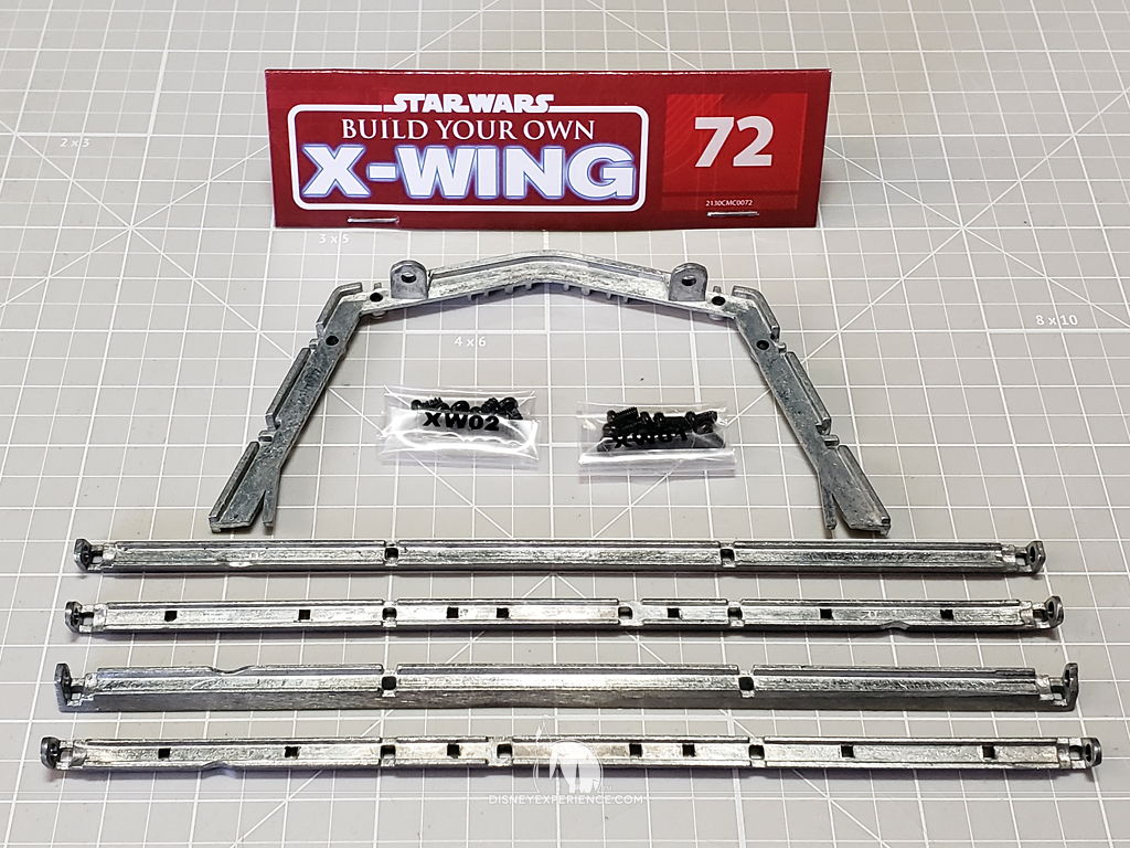
What’s Inside
The wings, motors, and electrical components are all assembled and ready for testing . . . almost. There are a couple of VERY IMPORTANT notes about testing.
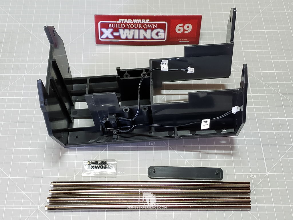

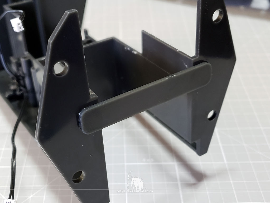
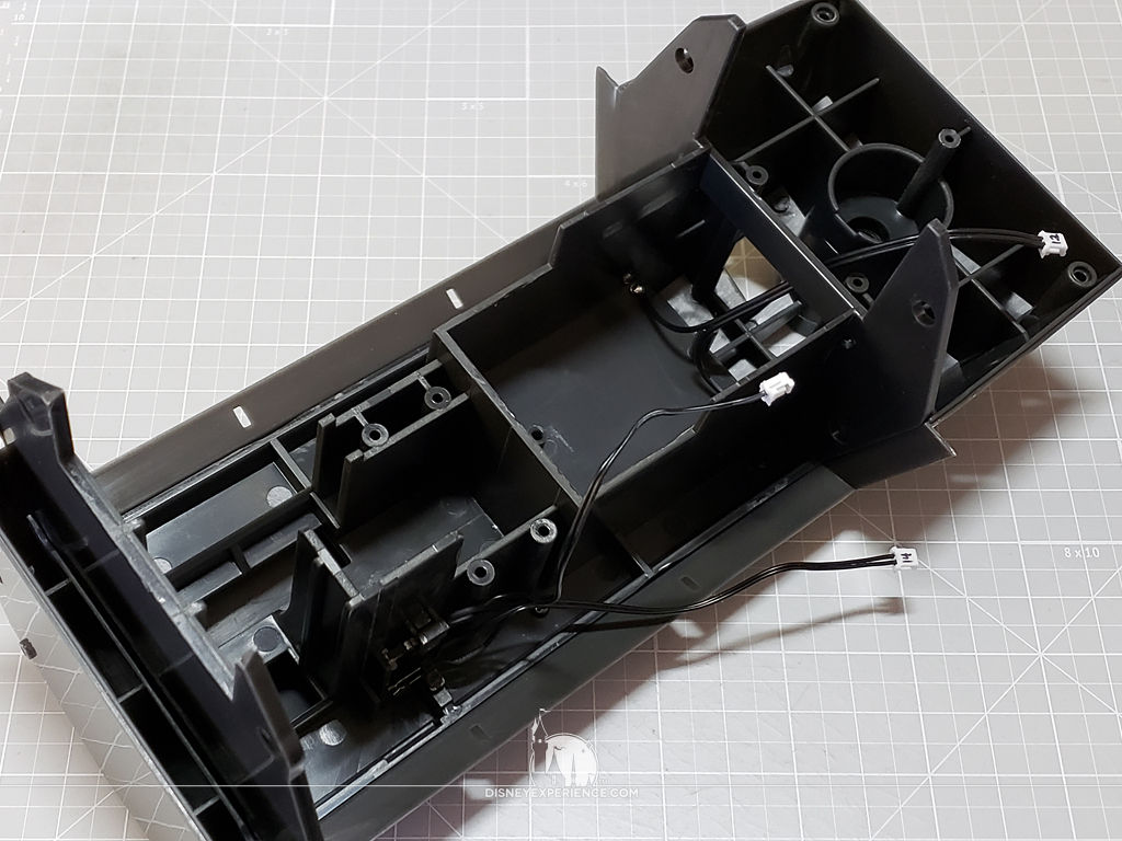
The Fuselage
Working very briefly on the fuselage, the only thing assembled is a support shelf and the wing mechanism support. Easy-peasy.
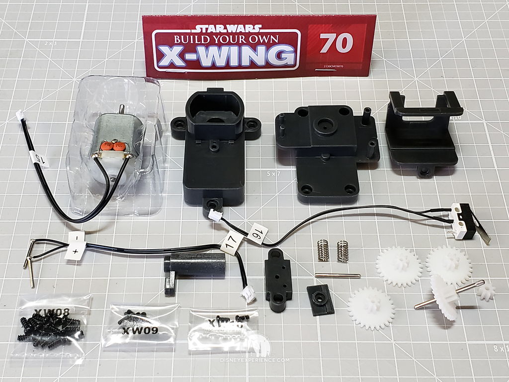
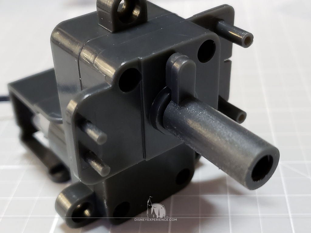
Assembling R2-D2’s Motor
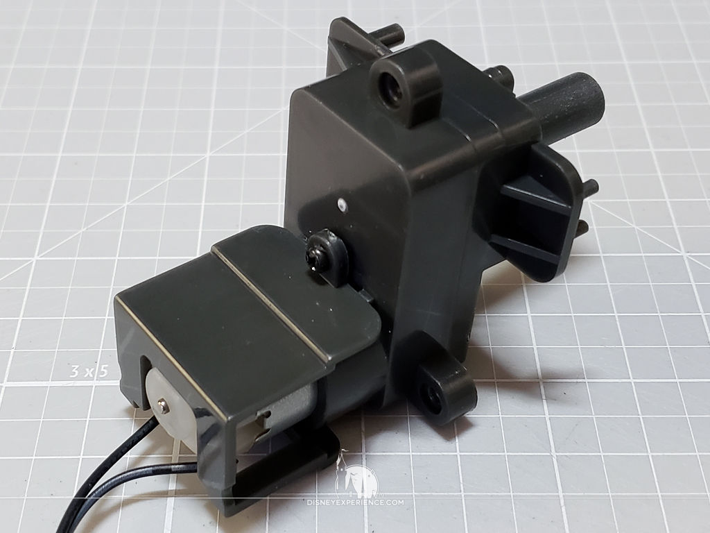
The motor that turns R2-D2’s head is a far less complex version of the motor for the wings.
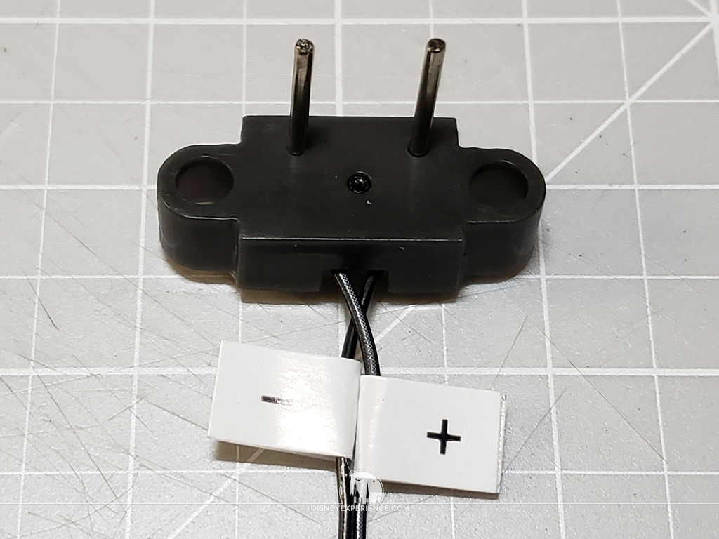
When I built the R2-D2 figure, I accidentally switched the contacts. Since I cannot take the figure apart, I had to switch the contact pins that get mounted to the motor. A quick test with the battery tester confirms that they do work.
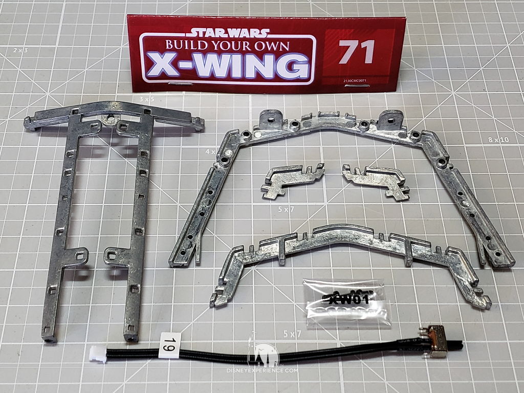
Putting It All Together
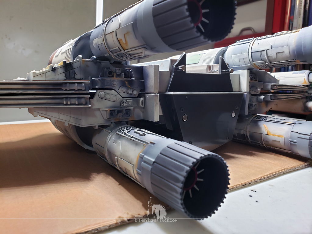
At this stage, the instructions say to remove the laser cannons so that they don’t accidentally get broken. They do stick out quite a bit, making storage a bit of a problem. But, my cannons are permanently glued into place (except for the tips), so I will have to be extra careful.
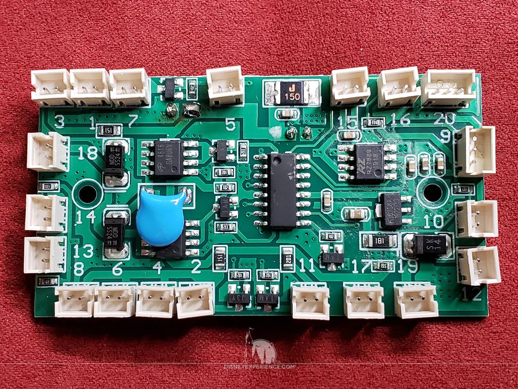
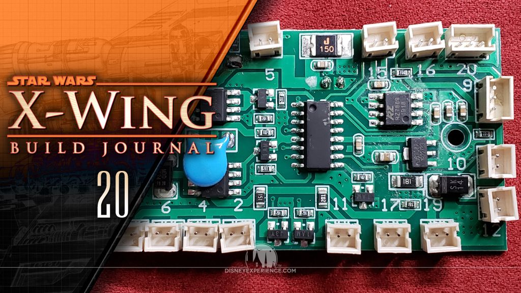
The very first thing that I noticed was that my circuit board looked different from the diagram in Issue 71. The general layout was the same—aside from some different chips—but, the plugs were numbered differently. This is a noted problem in the US and Germany magazines. The correct diagram is as follows:
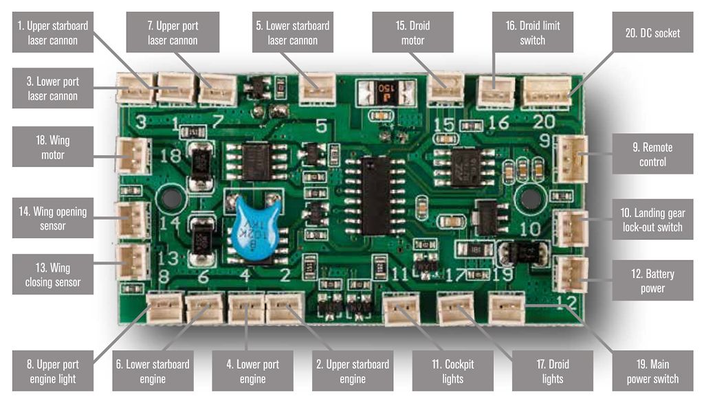
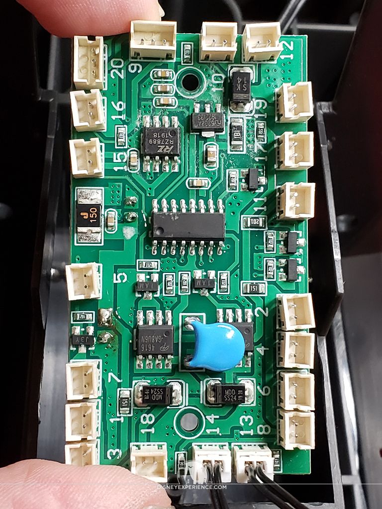
Ignoring the circuit board diagram in the magazine, I continued with the instructions, plugging in the electrical components according to the numbers printed on the circuit board.
After the four wings have been plugged in, the wing motor is mounted to the fuselage. Then, the four spindle rods are inserted to lock the wings into place.
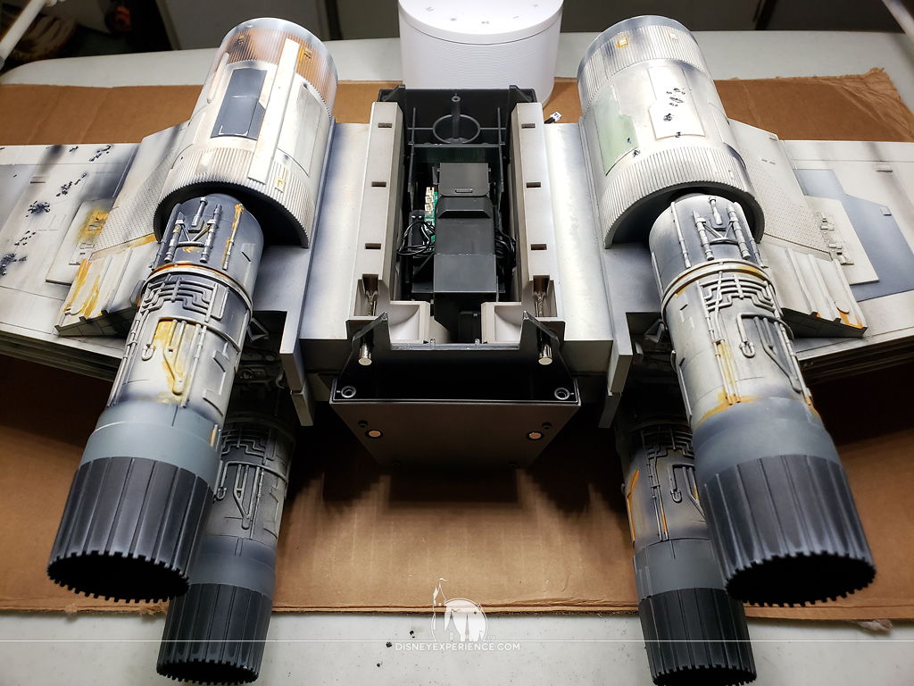
I noticed that the wings have a slight bow to them, which means they don’t lay flat. This appears to be a common defect, and it can apparently cause the wing motor to not shut off, potentially stripping gear teeth. There is a proposed solution by other builders.
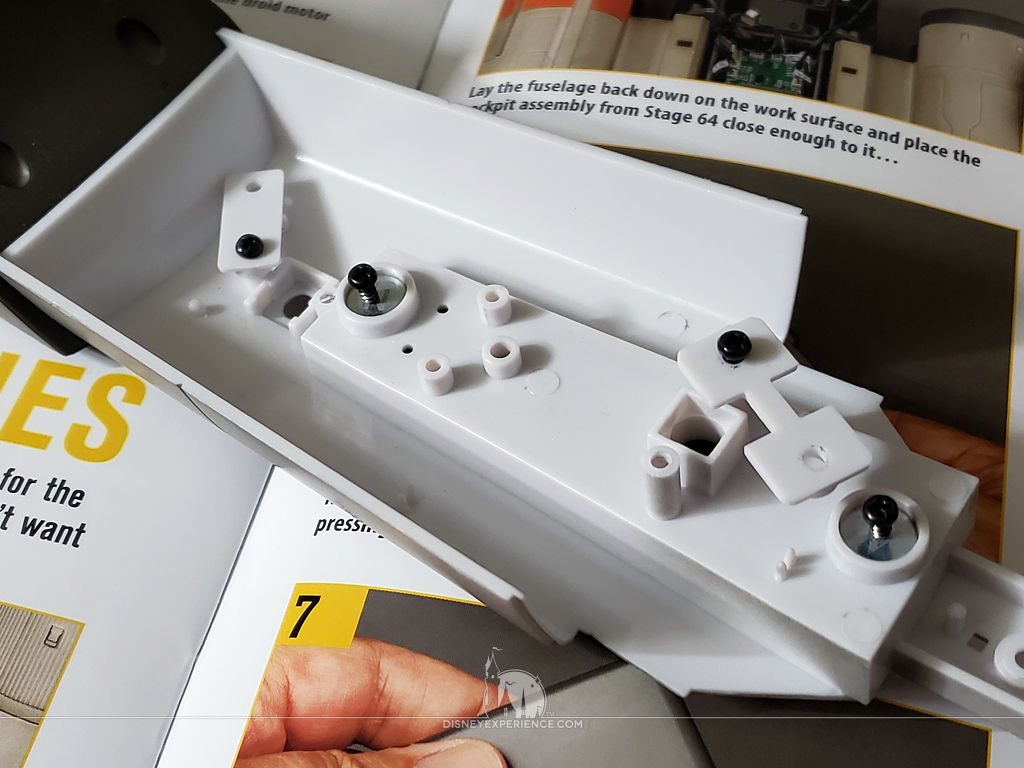
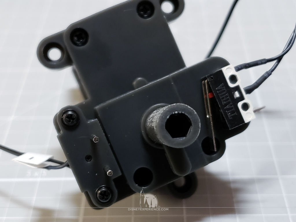
For testing purposes, both the antenna and the landing gear lock-out switch need to be removed from the nose section and plugged into the circuit board. For each component, I simply removed one screw and loosed the other. The plates swivel out of the way, and the loose screws are held by the adjoining magnets to prevent loss.
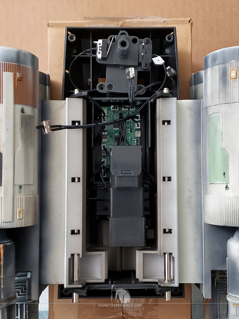
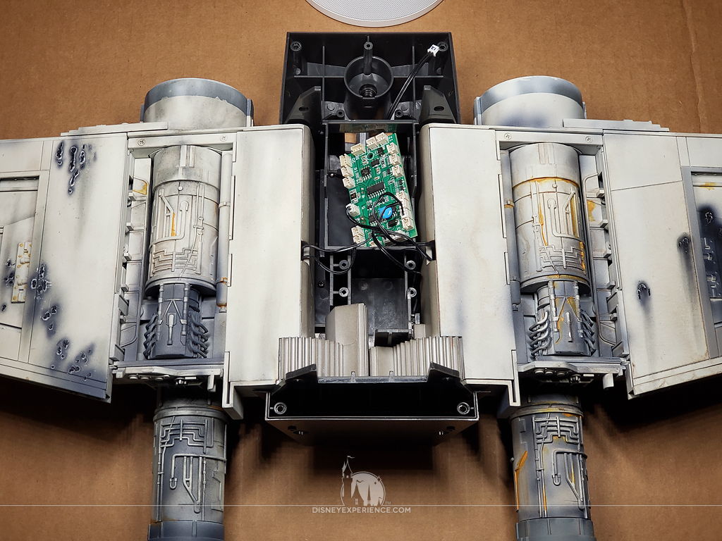
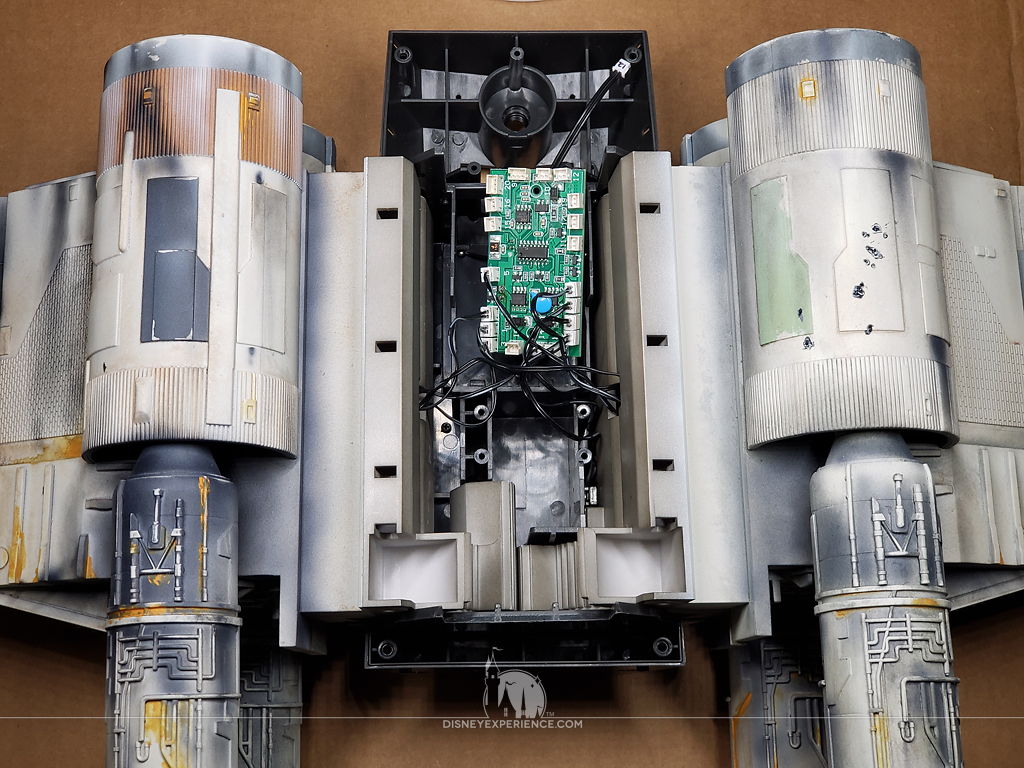
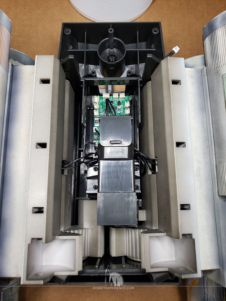
With the R2-D2 motor temporarily installed, and all of the electrical components (cockpit not pictured) plugged into the circuit board, I began a hair-pulling evening of testing. Nothing worked, and I couldn’t pinpoint the problem. Were the batteries dead? Did I assemble the remote incorrectly? Was my circuit board defective? Was my antenna defective? Is the power plug defective? Is my main switch defective? Are there more than one defective items? There are so many possibilities! Which brings me to . . .
Important Notes About Testing the Electronics
DO NOT TEST!
I was driving myself insane looking for a solution—then, I found one. Looking on the ModelSpace forum, there was quiet little post about testing the electronics. IT . . . WON’T . . . WORK!
Issue 72 says to test everything by installing batteries and using the remote. However, the instructions leave out the fact that there is a DC connector that is needed to be plugged into the remaining empty port on the circuit board. Without this part plugged in, nothing will work, which defeats the purpose of attempting any testing. Why were the testing instructions ever included in this issue!? The DC connector comes with Issue 74, which is when I will be able to finally test the electronics.
ModelSpace has also made it clear that impatient builders should not attempt to manually bridge the connection on the circuit board. This will cause the board to burn out, and a FREE replacement WILL NOT be sent out. A new one will have to be PURCHASED instead.
WHY is this notice quietly tucked away on an obscure forum that not every builder visits or reads!? This could have been handled better; a simple flyer in the box would have sufficed.
Remote Control Sticker
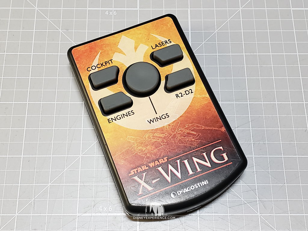
I finally created a sticker label for the remote control. I had been putting it off for a while, and I eventually forgot about it. But, I did finish it, and it is available for everyone to download. Be sure to print it onto sticker paper, and use a sharp craft knife to cut out the 5 holes in the sticker.
Prev Journal Entry | Next Journal Entry
Both the post author and this website have not received any compensation for writing this post. Both the post author and this website have no material connection to the third-party brands, products, or services that have been mentioned. Some of the links in the post above are “affiliate links.” This means that if you purchase the item, we will receive a commission. As an Amazon associate, we earn from qualifying products. This is being disclosed in accordance with the Federal Trade Commission’s 16 CFR, Part 255: “Guides Concerning the Use of Endorsements and Testimonials in Advertising.”
Do you have a thought about this post? Why not leave a comment . . .