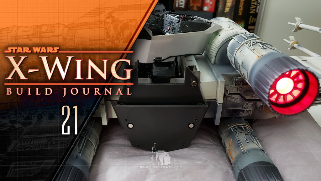
X-Wing Build Journal No. 21: Issues 73-76
Trader Sam | November 30, 2020
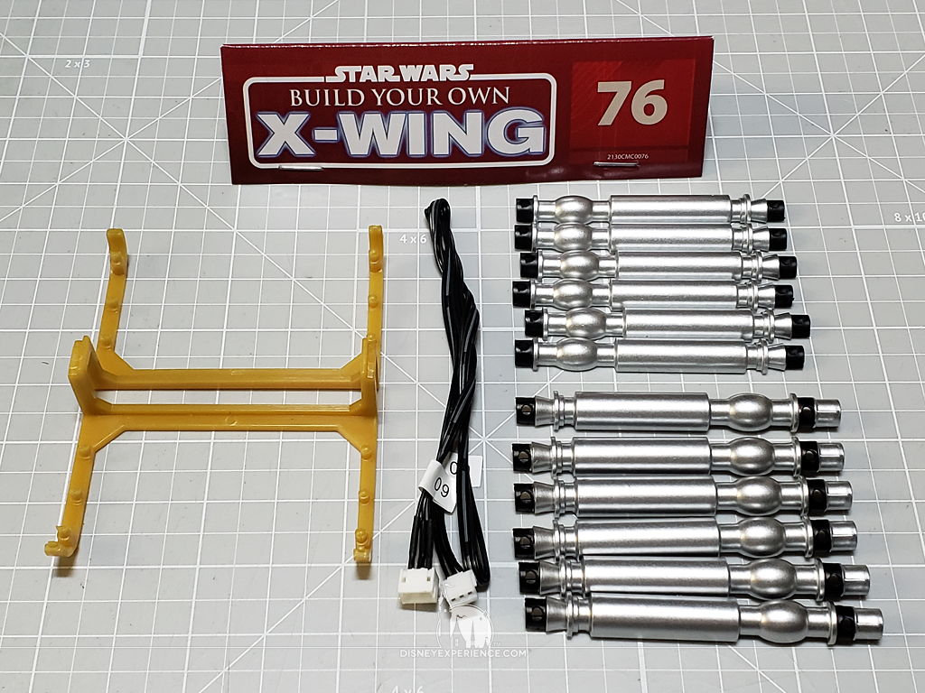
What’s Inside
I finally get to properly test the electronics, and I run into a major snag with malfunctioning wings.

Testing the Electronics
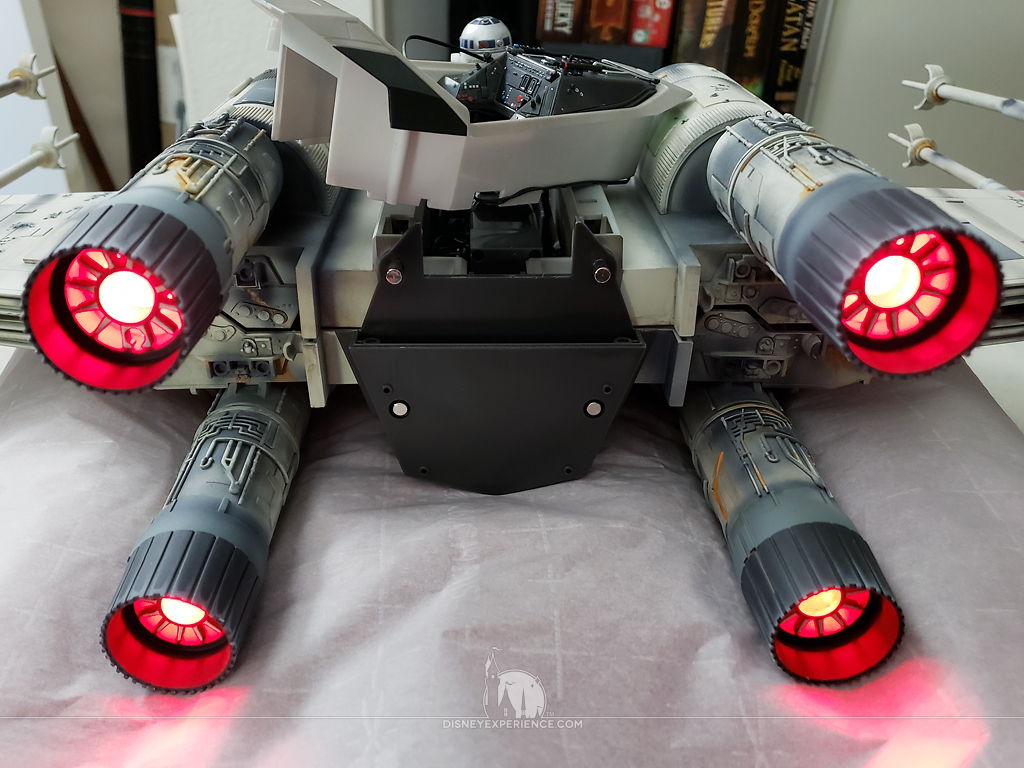
Now that I had the required part (the DC input) to properly test the electronics, I was able to get everything working. First, I tested both the engine lights & the laser cannons, . . .
. . . and I took the opportunity to label the main switch’s “on” and “off” positions (‘1’ for “on,” and a ‘0’ for “off”).
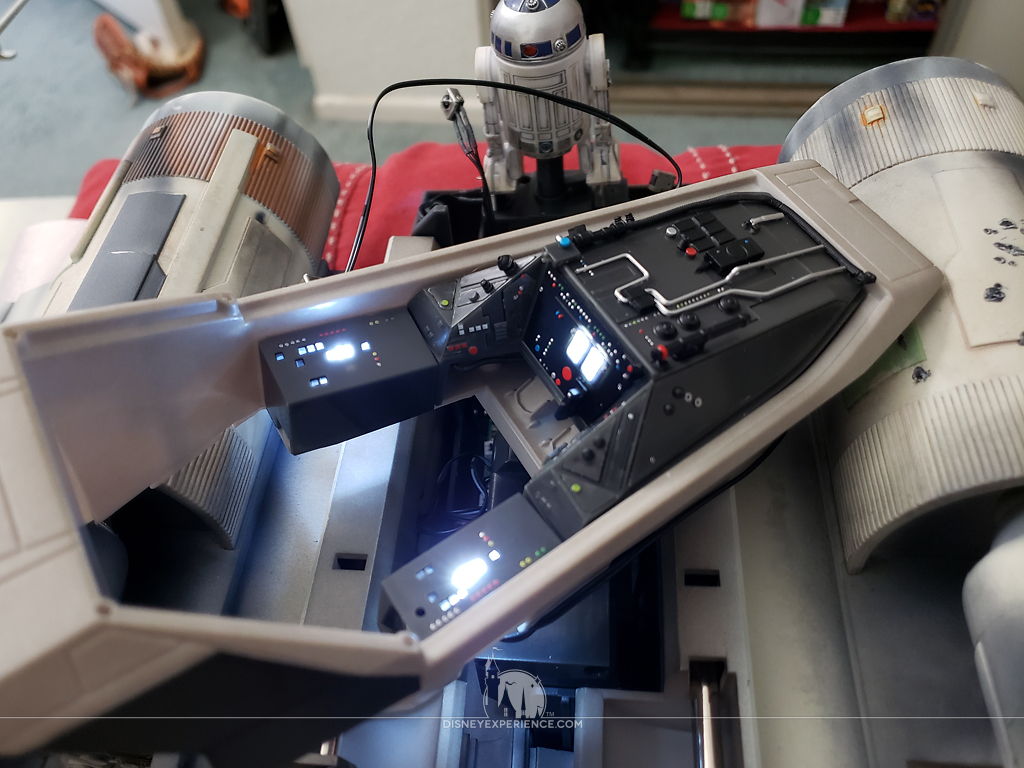
Next, I tested the cockpit lights and R2-D2. Everything works—except for the wings. Don’t misunderstand; the wings do “work,” but they malfunction due to a common defect in the manufacturing process.
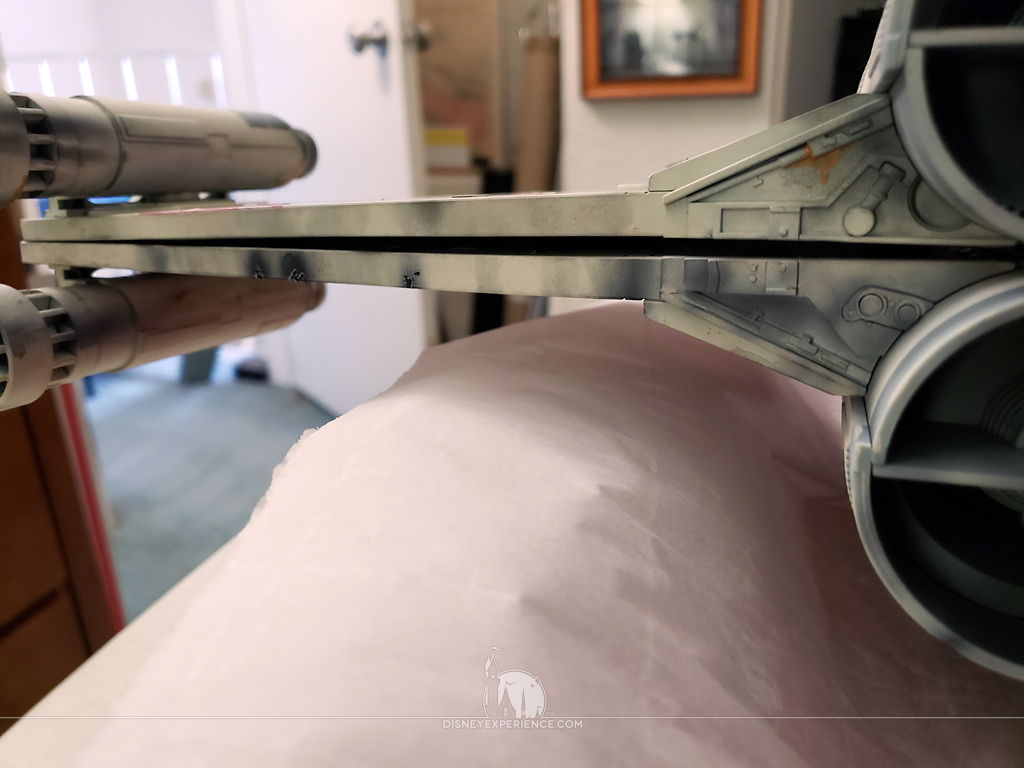
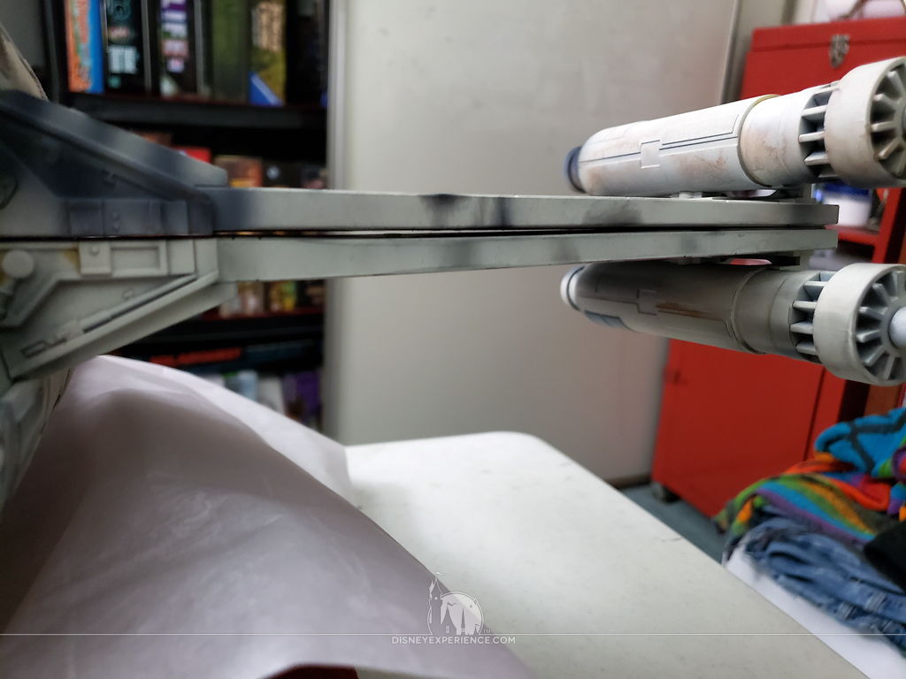
You see, the wings are not completely flat; they have a slight curve that prevents them from closing all of the way.
Inside of the fuselage, there are two limit switches that turn the wings’ motor off when one of two tabs comes into contact with them. These tell the electronics when the wings are in their open or closed positions. Since the wings cannot fully close, the tab that is supposed to trigger the limit switch cannot reach. That leaves the motor spinning, and the gears click loudly, potentially stripping the teeth. It’s a horrible, scary sound. Fortunately, I knew about this problem, and I had my hand on the X-Wing’s main on/off switch when I first tested the wings.
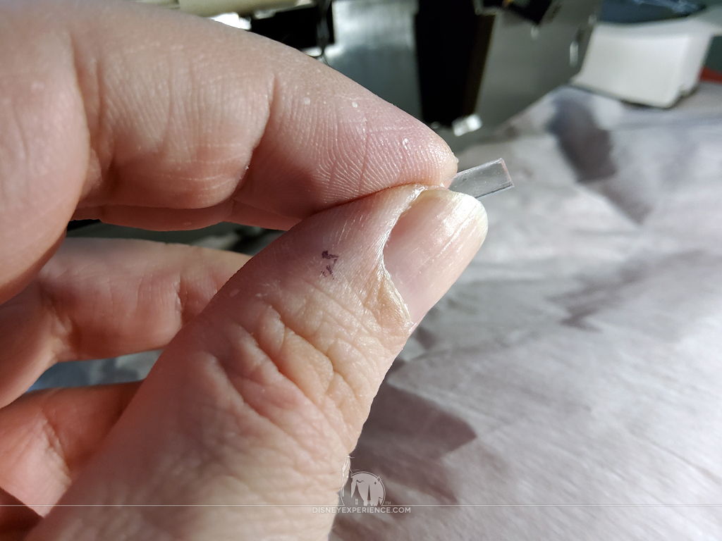
To fix the issue, I took some advice from the Model Space forum community. I created a tiny, 1mm-thick shim which I then glued to the tab that tells the motor to stop when the wings are closed. Since i could not find a piece of plastic that thick, I cemented two small scrap pieces of .015 clear plastic sheeting. Using Tamiya extra thin cement, the pieces bonded instantly.
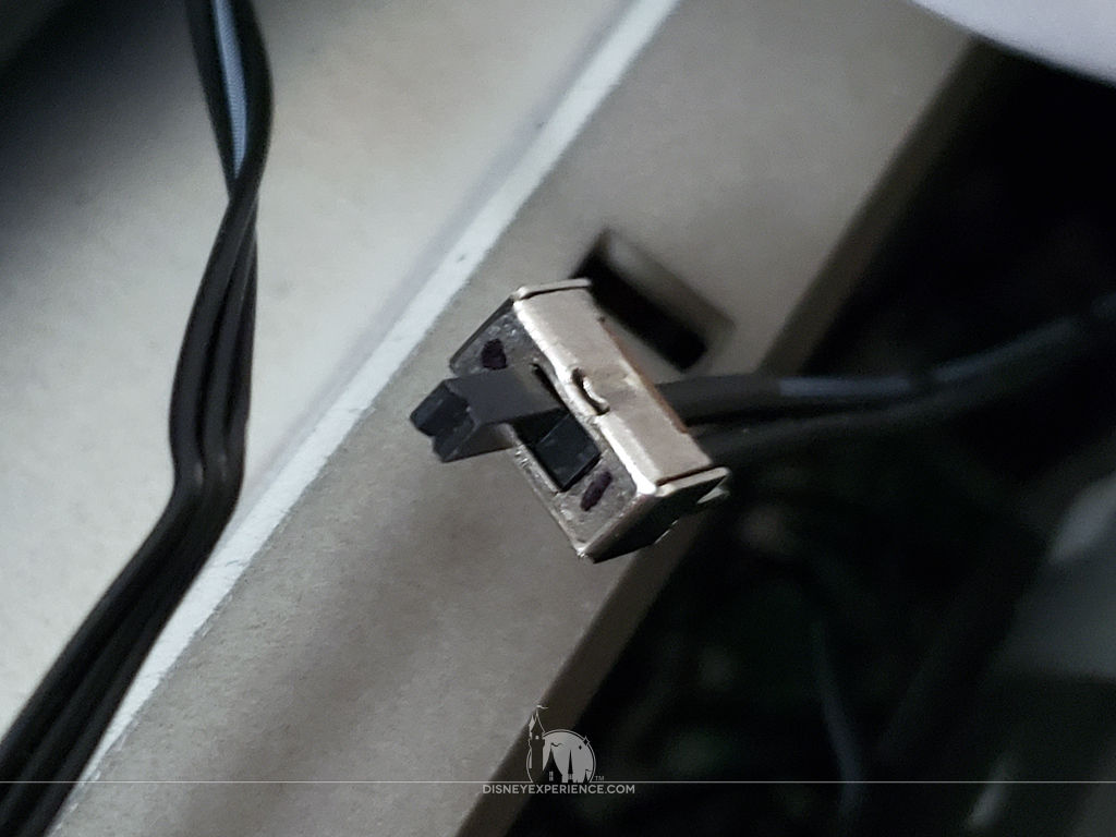
The next part, unfortunately, requires removing the wings, loosening the wing motor, and unplugging wires from the circuit board. Everything is a tight fit, and messing with a fragile circuit board is scary. Plus, the sockets kept pulling off of the circuit board along with the plugs, and I had to carefully push them back onto the exposed metal pins.
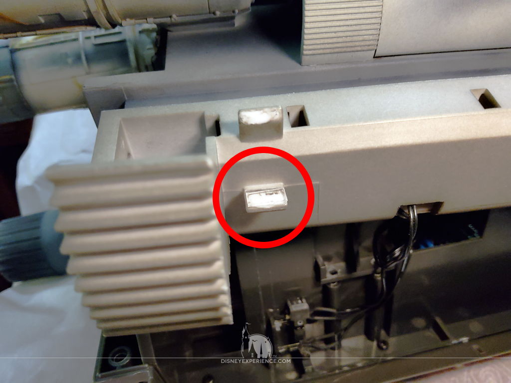
The two limit switch tabs are located on the lower starboard wing, and only one of them (the one closest to the wing’s gear teeth) needs the shim. I trimmed the shim down to size and glued it to to the side that contacts the limit switch (pictured). With the shim in place, I had to re-assemble the wings, making sure that the teeth are meshed together in the correct position (as illustrated in Step 5 on page 14 of Issue 71).
I powered the X-Wing on after plugging all of the wires back in, and I was happy to see that the wings now worked properly. Yes, there are still those gaps between the wings, but they are not horrible to look at. And, I really don’t know how to bend the wings without breaking them. With the headaches that the electronics have been giving me, I’m going to cut my losses and just move on. I’m happy now, and the gaps are acceptable.
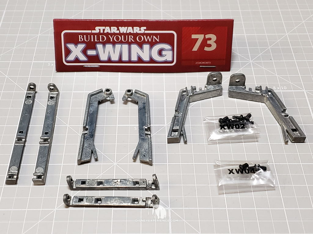
More Fuselage Work
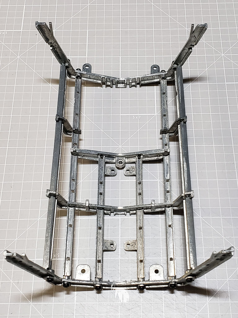
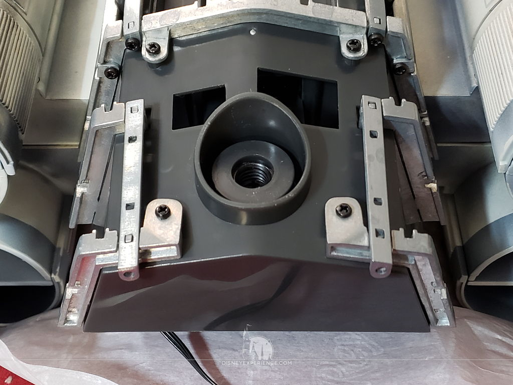
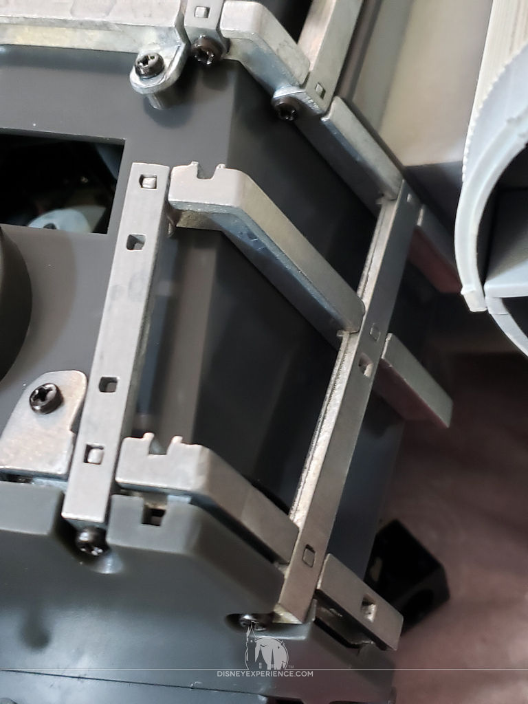
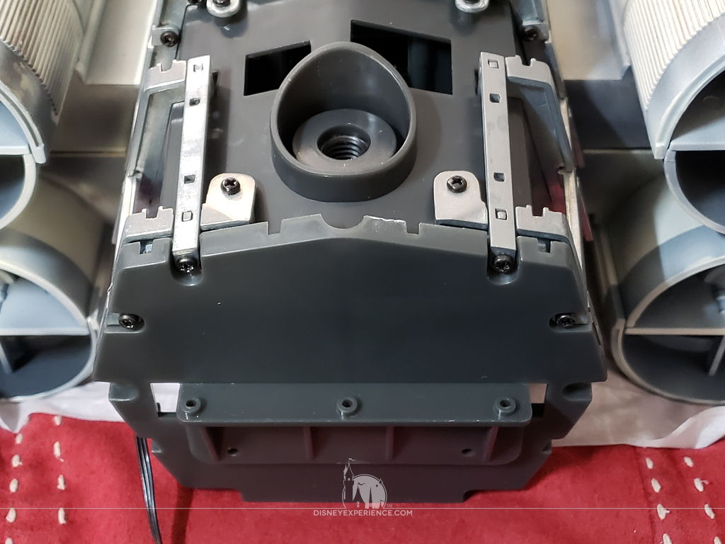
The fuselage now gets some metal framework attached to it. Unlike the nose frame, these pieces are labeled “L” and “R,” which makes assembly a lot easier.
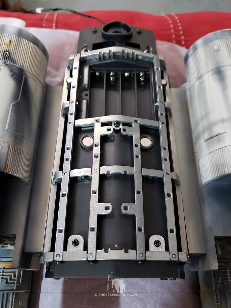
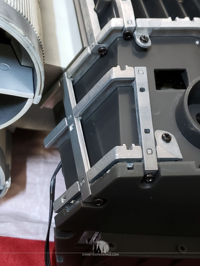
Most of the frame is constructed separately, and attached to the fuselage as a whole. A few pieces at the end, where the cockpit will eventually connect, are added to the fuselage one at a time.
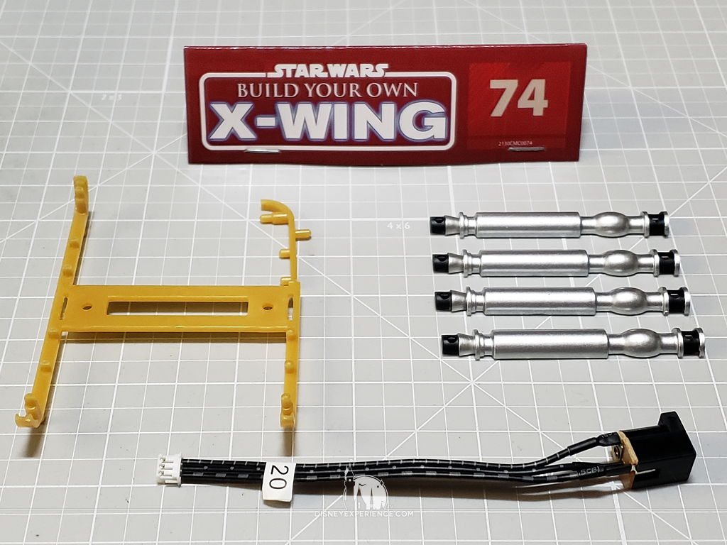
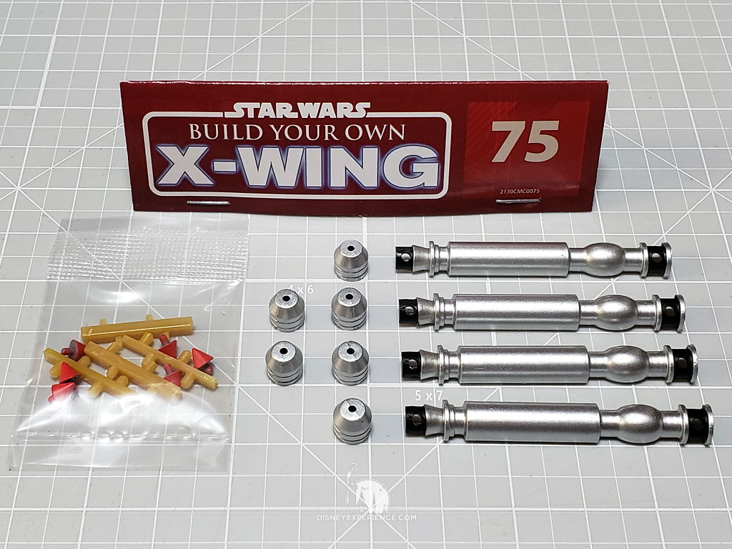
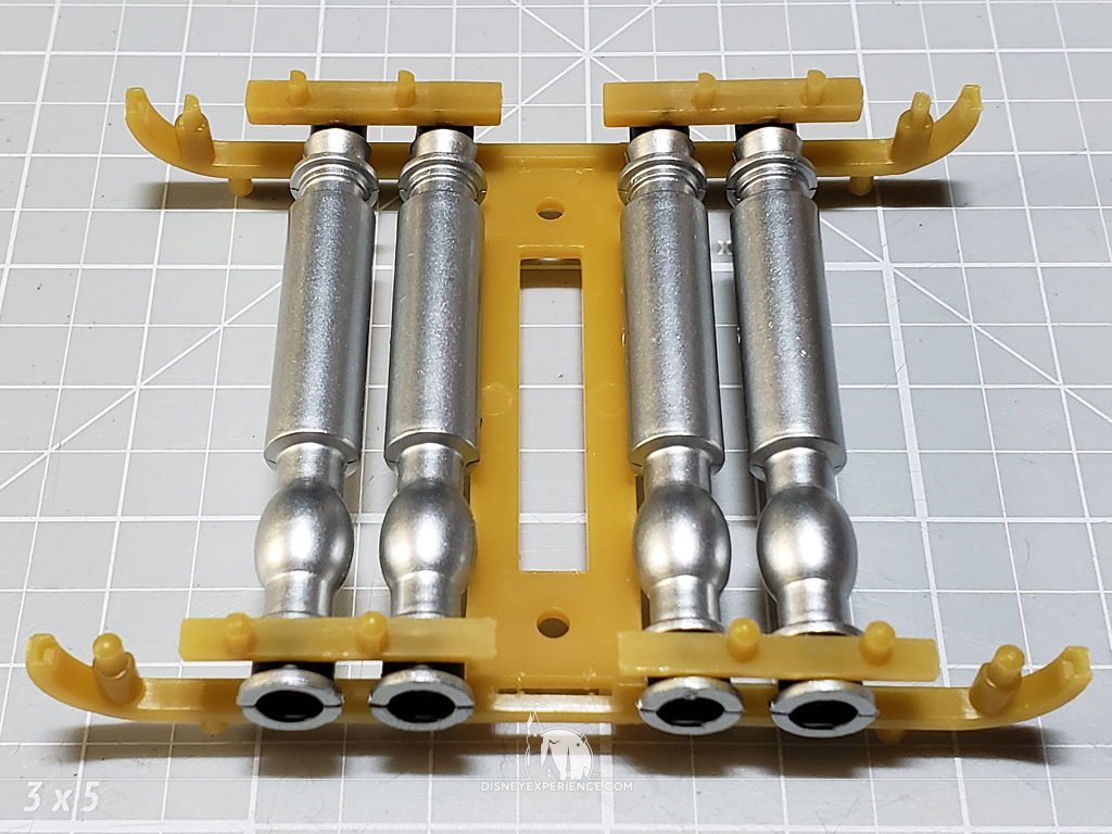
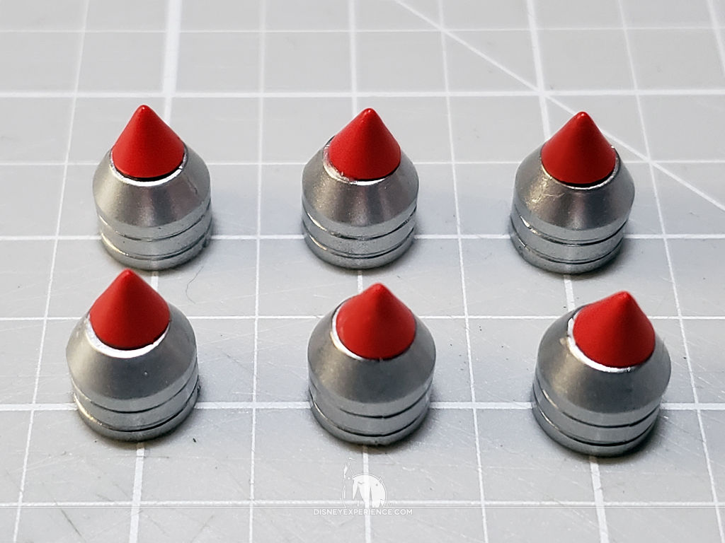
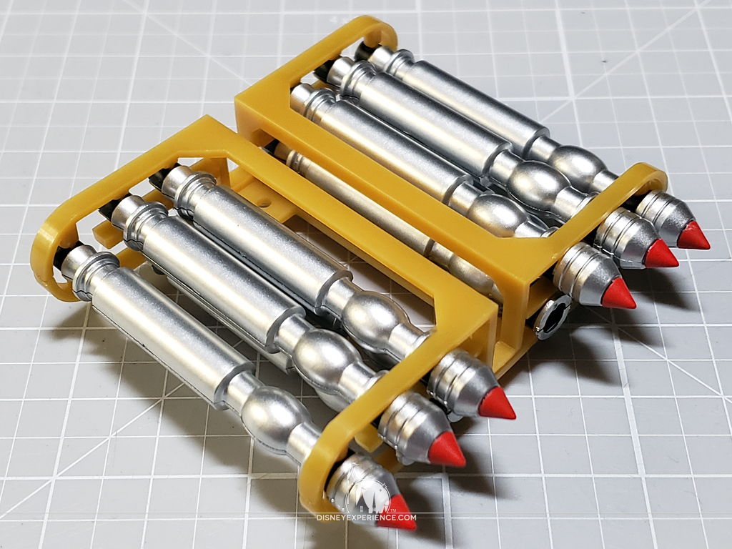
The Torpedo Rack
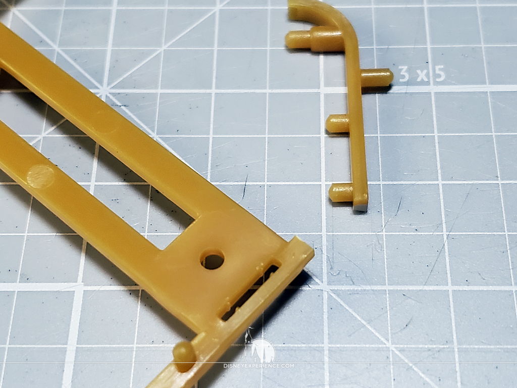
One of the torpedo rack pieces arrived broken. It was a clean break, and it cemented together easily.
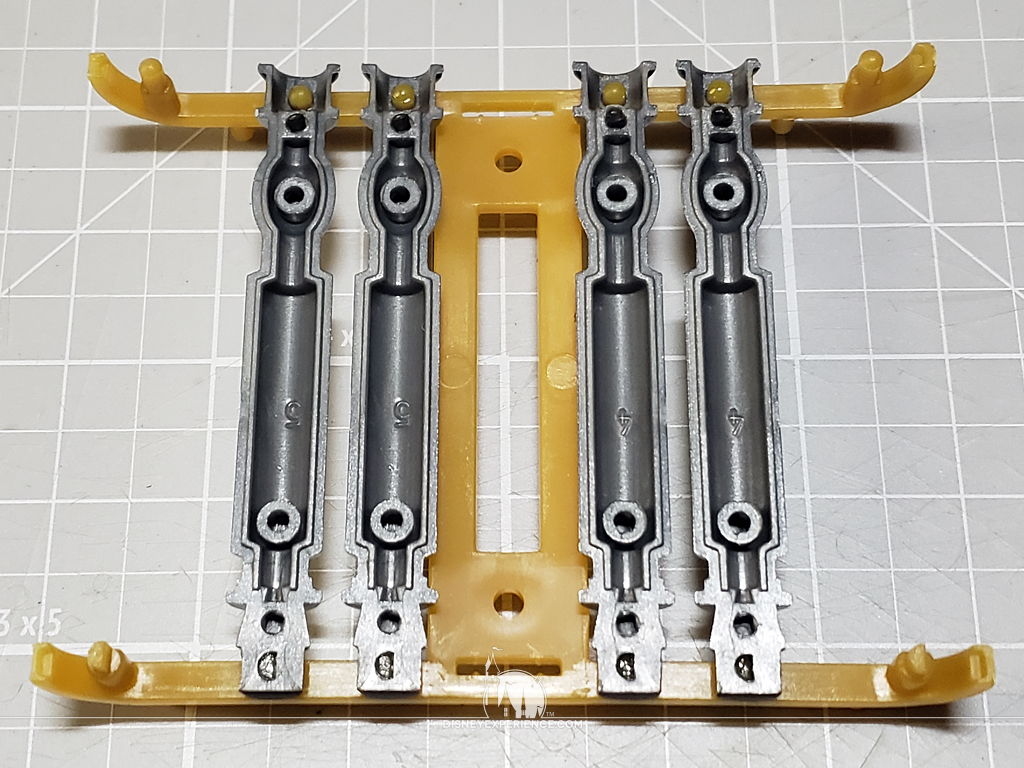
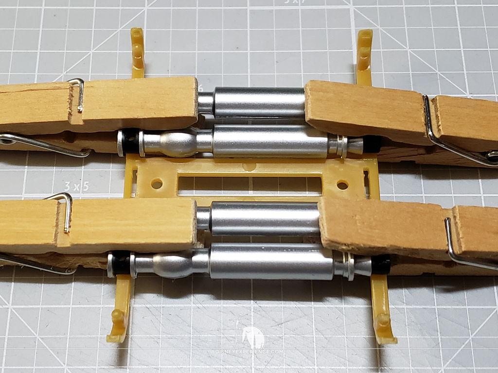
Because I washed these pieces (I may weather them later), the torpedo parts were all jumbled. They look very similar, but it was important to sort them out before assembly. I also had to use clothes pins to keep the two halves of the torpedoes together while the cement dried.
I hope that future months will have smoother assemblies.
Prev Journal Entry | Next Journal Entry
Both the post author and this website have not received any compensation for writing this post. Both the post author and this website have no material connection to the third-party brands, products, or services that have been mentioned. Some of the links in the post above are “affiliate links.” This means that if you purchase the item, we will receive a commission. As an Amazon associate, we earn from qualifying products. This is being disclosed in accordance with the Federal Trade Commission’s 16 CFR, Part 255: “Guides Concerning the Use of Endorsements and Testimonials in Advertising.”
Do you have a thought about this post? Why not leave a comment . . .