Designing a Paper Model
Introduction by Trader Sam
 I often get questions regarding how I design Disney paper models, and how others can make their own. There is no single answer since many paper model designers have their own methods. There is no right or wrong way to go, no single program to use. All I can do is reveal how I do them.
My methods have changed over the years, but this is the latest. Hopefully, it will answer many questions, and inspire others.
The model I will be focusing on is the Disneyland® Paris Sleeping Beauty Castle that I designed. Designing a paper model from scratch is very time consuming, and a lot of hard work! Not that it isn't enjoyable.
Part 1: The Basic Shape
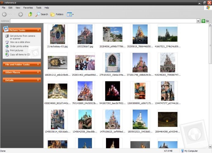
Gathering reference photos is a must! Sources come from the Internet, movie image captures, and photos of replica props. Some photos even come from site guests. But, the VERY BEST images are blueprint elevations and dead-on photos. They provide the best placement accuracy.
I only have photos to work from, so this model will take a little longer than if I had side elevations. Perspective in the photos is the enemy since shapes and sizes are distorted.
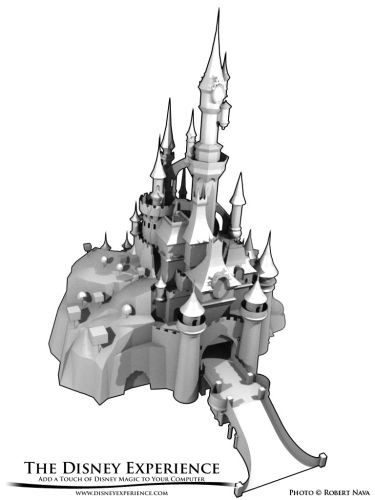
Paper models are rendered in Blender, a CG modeling program. This makes the models very accurate, and that means I don't have to make as many corrections as I used to.
In the old days, I had to re-teach myself high school Geometry and imagine the shapes in my head. One head-scratcher was figuring out how to trisect an angle. I also had to limit models to those that could be broken into simple shapes.
I typically design the models to be printed with regular printer paper. The average computer users generally have printer paper readily available, so they can start printing right away. More experienced builders prefer to print onto a type of card stock (everyone has their own preferences) for greater sturdiness. Those who use regular paper are still amazed at how sturdy my models turn out.
For more sculptural models, I like to make them large, using 50 or more printed sheets of parts. For more toy-like or desktop models, I scale them down appropriately.
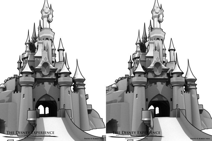
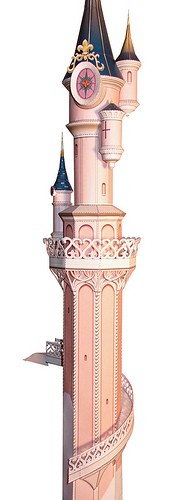
Here is a stereoscopic rendering of the nearly-final CG model. Cross your eyes and focus on the overlapping center image to see what the model looks like in 3-D.
Although the model looks detailed, many faces are flat and featureless. It's not until graphics are added that I can paint in illusions of depth.
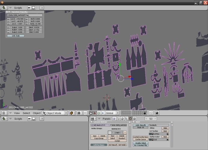
Model parts are broken down piece-by-piece. Blender 2.46 has a built-in Unfold Python Script that makes unfolding easy. I can even mark seams so that piece unfold the way I want them to.
The final file is exported as a Lightwave file.
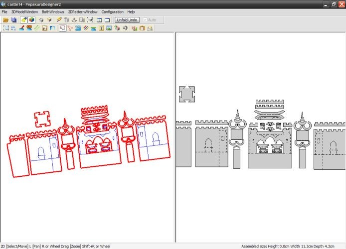
Lightwave files are one of the types of CG files that is supported by Pepakura Designer. Here, I can arrange all of the pieces, making them level and centered. Level parts are important for both adding graphics and creating nice page layouts.
Part 2: Graphics
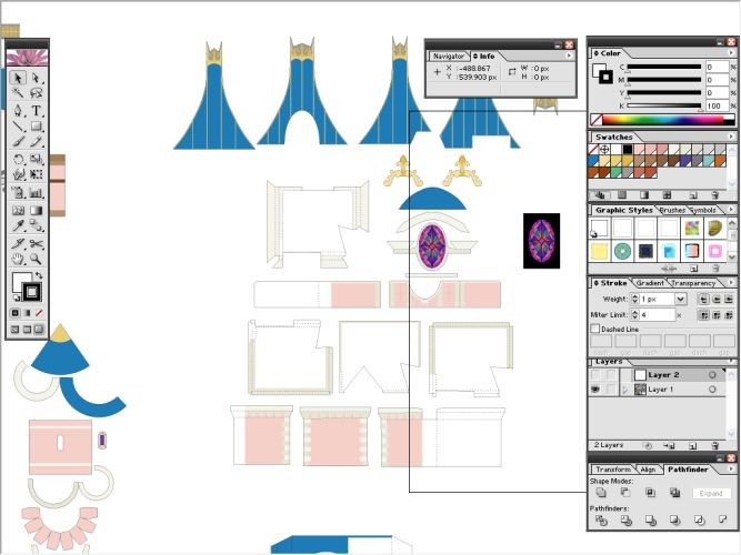
The pieces are transferred to Adobe Illustrator where color and basic details are added.
Adjacent shapes of the same final color are distinguished by using slightly differing colors. In this way, I will know where the edges of the shapes are, and can more easily apply special effects in Photoshop.
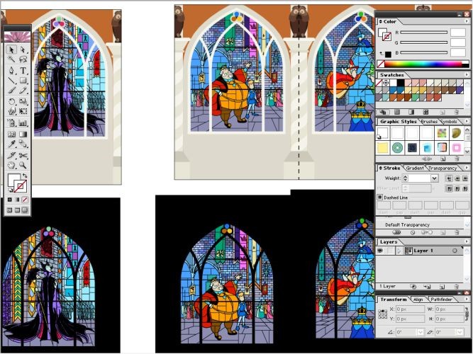
Some advanced graphics, like these stained glass windows, can be designed better in Illustrator rather than Photoshop. Some objects will be very small when printed, so focusing on too many of the tiny details (the faces and subtle designs in this instance) would waste valuable design time.
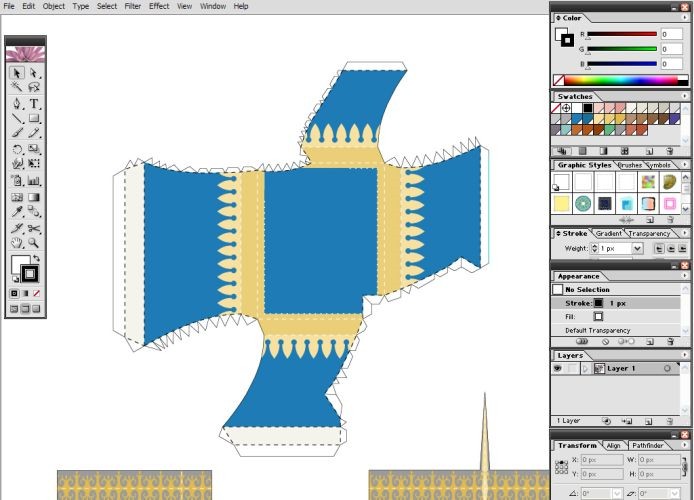
Next, tabs and extra fold lines are added.
When finished, the parts are separated and sized to fit onto individual 8'' x 10.5'' layers. This size will fit neatly onto the center of 8.5'' x 11'' paper, taking into account that printers typically do not print within a certain area along the edges of the paper.
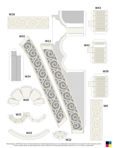
In the lower, right corner, a simple registration pattern is placed. This is mainly for users to diagnose any print/sizing errors if parts do not fit together properly. In some cases, printer settings may be changed accidentally, and some sheets may be printed at a different scale. Holding two sheets up to a light source and comparing the registration marks tells the user whether the mistake is a printer error or my own error.

Each sheet image is saved as a 300 dpi bitmap and imported into Photoshop for detailing. The final, printed sheet will be 150 dpi, but the larger size lets me add more detail while I work.
Custom graphics are typical of most designs. Some graphics can be tiled to quickly fill an entire region.
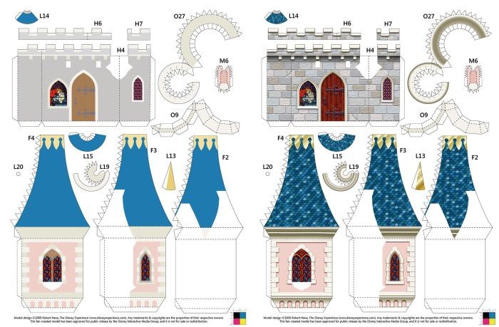
With some lighting, shadows, textures, and masks, the required effects are achieved. In this instance, some three-dimensional effects give the flat pieces depth.
When all of the pages are complete, they are all converted to PDF files for printing.
Part 3: Building the Prototype
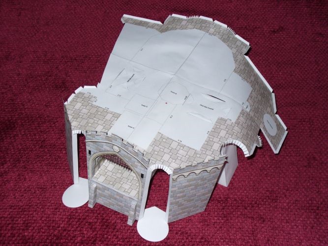
With the final graphics completed, construction begins on the model prototype (which I usually keep for myself). During construction, graphical mistakes and physical defects are noted and corrected before construction continues.
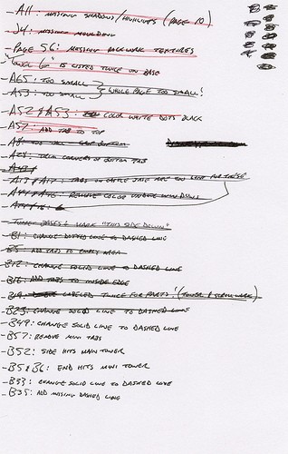
As I build the prototype model, I note any errors or corrections that are needed. I spend a portion of the afternoon making corrections to the files. Then, I spend a portion of the evenings building the model.
Great care is taken when cutting, scoring, and gluing. It can often take a few hours just to assemble 5-6 pieces. Accuracy is important.
Some parts are cut out using a plotter cutter, a machine that can cut out shapes. Think of it as an automated craft knife. I use the Craft ROBO. Unfortunately, it can't do delicate pieces without ripping them to shreds, so they are partly cut by hand.
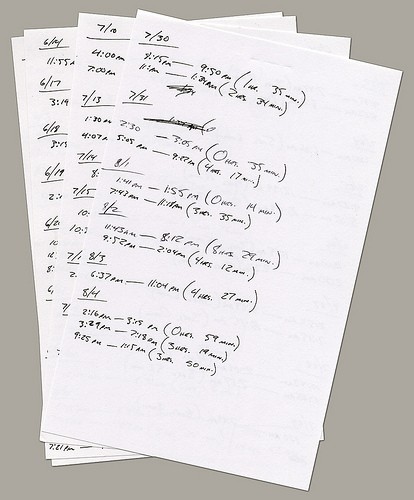
I keep a record of the days and times that I work on the model from the very beginning. At this point, I have worked well over 400 hours on this particular model.
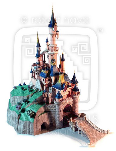
Here is the completed model.
Both the post author and this website have not received any compensation for writing this post. Both the post author and this website have no material connection to the third-party brands, products, or services that have been mentioned unless otherwise explicitly stated. Some of the links in the post above are "affiliate links." This means that if you purchase the item, we will receive a commission. As an Amazon associate, we earn from qualifying products. This is being disclosed in accordance with the Federal Trade Commission's 16 CFR, Part 255: "Guides Concerning the Use of Endorsements and Testimonials in Advertising."